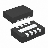
LT1965EDD#TRPBF Linear Technology, LT1965EDD#TRPBF Datasheet - Page 13

LT1965EDD#TRPBF
Manufacturer Part Number
LT1965EDD#TRPBF
Description
IC REG LDO 1.1A 8-DFN
Manufacturer
Linear Technology
Datasheet
1.LT1965EDD-3.3PBF.pdf
(20 pages)
Specifications of LT1965EDD#TRPBF
Regulator Topology
Positive Adjustable
Voltage - Output
1.2 ~ 19.5 V
Voltage - Input
1.8 ~ 20 V
Voltage - Dropout (typical)
0.31V @ 1.1A
Number Of Regulators
1
Current - Output
1.1A
Current - Limit (min)
1.2A
Operating Temperature
-40°C ~ 125°C
Mounting Type
Surface Mount
Package / Case
8-DFN
Lead Free Status / RoHS Status
Lead free / RoHS Compliant
Available stocks
Company
Part Number
Manufacturer
Quantity
Price
APPLICATIONS INFORMATION
capacitor values below appropriate levels. Capacitor DC
bias characteristics tend to improve as component case
size increases, but expected capacitance at operating
voltages should be verifi ed.
Voltage and temperature coeffi cients are not the only
sources of problems. Some ceramic capacitors have a
piezoelectric response. A piezoelectric device generates
voltage across its terminals due to mechanical stress,
similar to the way a piezoelectric accelerometer or micro-
phone works. For a ceramic capacitor, the stress can be
induced by vibrations in the system or thermal transients.
The resulting voltages produced can cause appreciable
amounts of noise. A ceramic capacitor produced the trace
in Figure 5 in response to light tapping from a pencil.
Similar vibration induced behavior can masquerade as
increased output voltage noise.
Figure 3. Ceramic Capacitor DC Bias Characteristics
–100
–20
–40
–60
–80
20
0
0
2
4
DC BIAS VOLTAGE (V)
BOTH CAPACITORS ARE 16V,
1210 CASE SIZE, 10μF
6
8
Y5V
X5R
Figure 5. Noise Resulting from Tapping on a Ceramic Capacitor
10
12
1mV/DIV
14
1965 F03
16
V
C
I
LOAD
OUT
OUT
= 1.3V
= 10μF
= 0
1ms/DIV
Overload Recovery
Like many IC power regulators, the LT1965 has safe oper-
ating area protection. The safe area protection decreases
current limit as input-to-output voltage increases and keeps
the power transistor inside a safe operating region for all
values of input-to-output voltage. The protective design
provides some output current at all values of input-to-
output voltage up to the device breakdown.
When power is fi rst applied, as input voltage rises, the
output follows the input, allowing the regulator to start up
into very heavy loads. During start-up, as the input voltage
is rising, the input-to-output voltage differential is small,
allowing the regulator to supply large output currents.
With a high input voltage, a problem can occur wherein
removal of an output short will not allow the output to
Figure 4. Ceramic Capacitor Temperature Characteristics
–100
1965 F05
–20
–40
–60
–80
40
20
0
–50
BOTH CAPACITORS ARE 16V,
1210 CASE SIZE, 10μF
–25
0
TEMPERATURE (°C)
25
LT1965 Series
50
Y5V
75
X5R
100
1965 F04
125
13
1965fa


