XR21V1412IL-0A-EB Exar Corporation, XR21V1412IL-0A-EB Datasheet - Page 17
XR21V1412IL-0A-EB
Manufacturer Part Number
XR21V1412IL-0A-EB
Description
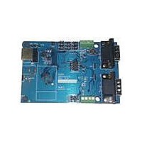
EVAL BOARD FOR XR21V1412IL
Manufacturer
Exar Corporation
Datasheet
1.XR21V1412IL32-F.pdf
(30 pages)
Specifications of XR21V1412IL-0A-EB
Main Purpose
Interface, Transceiver
Embedded
No
Utilized Ic / Part
XR21V1412IL
Interface Type
RS-232, RS-485, USB, UART
Operating Supply Voltage
3.3 V
Product
Interface Modules
Silicon Manufacturer
Exar
Silicon Core Number
XR21V1412
Kit Application Type
Interface
Application Sub Type
UART
Kit Contents
Board
For Use With/related Products
XR21V1412IL32-F
Lead Free Status / RoHS Status
Lead free / RoHS Compliant
Secondary Attributes
-
Primary Attributes
-
Lead Free Status / Rohs Status
Lead free / RoHS Compliant
Other names
1016-1301


REV. 1.1.0
This register enables the UART TX and RX. For proper functionality, the UART TX and RX must be enabled in
the following order:
UART_ENABLE[0]: Enable UART TX
UART_ENABLE[1]: Enable UART RX
UART_ENABLE[7:2]: Reserved
These bits are reserved and should remain ’0’.
These registers are used for programming the baud rate. The V1412 uses a 19-bit divisor and 16-bit mask
register. Using the internal 48MHz oscillator, the 19-bit divisor is calculated as follows:
For example, if the the baud rate is 115200bps, then
CLOCK_DIVISOR0[7:0]: Baud rate clock divisor bits [7:0]
CLOCK_DIVISOR1[7:0]: Baud rate clock divisor bits [15:8]
CLOCK_DIVISOR2[2:0]: Baud rate clock divisor bits [18:16]
CLOCK_DIVISOR2[7:3]: Reserved
These bits are reserved and should remain ’0’.
A look-up table is used for the value of the 16-bit TX Clock mask registers. The index of the look-up table is
calculated as follows:
For example, if the baud rate is 115200bps, then the index will be:
The values for some baud rates to program the TX_CLOCK_MASK registers are listed in
rates that are not listed, use the index to select TX_CLOCK_MASK register values from
The values for some baud rates to program the RX_CLOCK_MASK registers are listed in
rates that are not listed, use the same index calculated for the TX_CLOCK_MASK register to select
RX_CLOCK_MASK register values from
3.3
3.3.1
3.3.2
3.3.3
3.3.4
Logic 0 = UART TX disabled.
Logic 1 = UART TX enabled.
Logic 0 = UART RX disabled.
Logic 1 = UART RX enabled.
UART Register Descriptions
FIFO_ENABLE_CHx = 0x1
UART_ENABLE = 0x3
FIFO_ENABLE_CHx = 0x3
CLOCK_DIVISOR = Trunc ( 48000000 / Baud Rate )
CLOCK_DIVISOR = Trunc ( 48000000 / 115200 ) = Trunc (416.66667) = 416
index = Trunc ( ( ( 48000000 / Baud Rate ) - CLOCK_DIVISOR ) * 32)
index = Trunc ( ( ( 48000000 / 115200 ) - 416 ) * 32) = Trunc (21.3333) = 21
UART_ENABLE Register Description (Read/Write)
CLOCK_DIVISOR0, CLOCK_DIVISOR1, CLOCK_DIVISOR2 Register Description (Read/Write)
TX_CLOCK_MASK0, TX_CLOCK_MASK1 Register Description (Read/Write)
RX_CLOCK_MASK0, RX_CLOCK_MASK1 Register Description (Read/Write)
Table
// Enable TX FIFO
// Enable TX and RX of that channel
// Enable RX FIFO
9.
17
2-CH FULL-SPEED USB UART
Table
Table
Table
XR21V1412
9.
8. For baud
8. For baud
Related parts for XR21V1412IL-0A-EB
Image
Part Number
Description
Manufacturer
Datasheet
Request
R

Part Number:
Description:
2-ch Full-speed Usb Uart
Manufacturer:
Exar Corporation
Datasheet:
Part Number:
Description:
BiCMOS Fixed, Quad, Voltage Output, Single or Dual Supply 8-Bit Digital-to-Analog Converter
Manufacturer:
Exar Corporation
Datasheet:
Part Number:
Description:
Manufacturer:
Exar Corporation
Datasheet:
Part Number:
Description:
Voltage-Controlled Oscillator
Manufacturer:
Exar Corporation
Datasheet:
Part Number:
Description:
INTEGRATED LINE TRANSMITTER
Manufacturer:
Exar Corporation
Datasheet:
Part Number:
Description:
Monolithic Function Generator
Manufacturer:
Exar Corporation
Datasheet:
Part Number:
Description:
CMOS Microprocessor Compatible Double-Buffered 12-Bit Digital-to-Analog Converter
Manufacturer:
Exar Corporation
Datasheet:
Part Number:
Description:
CMOS 6 BIT HIGH SPEED ANALOG TO DIGITAL CONVERTER
Manufacturer:
Exar Corporation
Datasheet:
Part Number:
Description:
Manufacturer:
Exar Corporation
Datasheet:
Part Number:
Description:
Manufacturer:
Exar Corporation
Datasheet:
Part Number:
Description:
8-Channel, Voltage Output 10 MHz Input Bandwidth 8-Bit Multiplying DACs with Serial Digital Data Por
Manufacturer:
Exar Corporation
Datasheet:
Part Number:
Description:
15 V CMOS Multiplying10-Bit Digital-to-Analog Converter
Manufacturer:
Exar Corporation
Datasheet:
Part Number:
Description:
Monolithic Function Generator
Manufacturer:
Exar Corporation
Datasheet: