XR21V1412IL-0A-EB Exar Corporation, XR21V1412IL-0A-EB Datasheet - Page 23
XR21V1412IL-0A-EB
Manufacturer Part Number
XR21V1412IL-0A-EB
Description
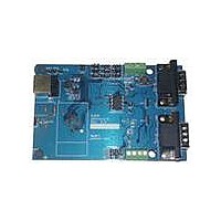
EVAL BOARD FOR XR21V1412IL
Manufacturer
Exar Corporation
Datasheet
1.XR21V1412IL32-F.pdf
(30 pages)
Specifications of XR21V1412IL-0A-EB
Main Purpose
Interface, Transceiver
Embedded
No
Utilized Ic / Part
XR21V1412IL
Interface Type
RS-232, RS-485, USB, UART
Operating Supply Voltage
3.3 V
Product
Interface Modules
Silicon Manufacturer
Exar
Silicon Core Number
XR21V1412
Kit Application Type
Interface
Application Sub Type
UART
Kit Contents
Board
For Use With/related Products
XR21V1412IL32-F
Lead Free Status / RoHS Status
Lead free / RoHS Compliant
Secondary Attributes
-
Primary Attributes
-
Lead Free Status / Rohs Status
Lead free / RoHS Compliant
Other names
1016-1301


REV. 1.1.0
GPIO_MODE[2:0]: GPIO Mode Select
There are 4 modes of operation for the GPIOs. The descriptions can be found in
page
GPIO_MODE[3]: Transceiver Enable Polarity
GPIO_MODE[7:4]: Reserved
These register bits are reserved. When writing to these bits, the value should be ’0’. When reading from these
bits, they are undefined and should be ignored.
This register controls the direction of the GPIO if it is not controlled by the GPIO_MODE register.
GPIO_DIRECTION[5:0]: GPIOx Direction
GPIO_DIRECTION[7:6]: Reserved
These register bits are reserved and should be ’0’.
Enables / disables generation of a USB interrupt packet at the change of state of GPIO pins when they are
configured as inputs.
GPIO_INT_MASK[5:0]: GPIOx Interrupt Mask
GPIO_INT_MASK[7:6]: Reserved
These register bits are reserved and should be ’0’.
3.3.11
3.3.12
3.3.13
Logic 0 = GPIO5 Low for TX
Logic 1 = GPIO5 High for TX
Logic 0 = GPIOx is an input.
Logic 1 = GPIOx is an output.
Logic 0 = A change on this input causes the device to generate an interrupt packet.
Logic 1 = A change on this input does not cause the device to generate an interrupt packet.
BITS
[2:0]
000
001
010
011
100
9.
GPIO_MODE Register Description (Read/Write)
GPIO_DIRECTION Register Description (Read/Write)
GPIO_INT_MASK Register Description (Read/Write)
GPIO0
GPIO0
GPIO0
GPIO0
GPIO0
GPIO0
GPIO1
GPIO1
GPIO1
GPIO1
GPIO1
GPIO1
GPIO2
GPIO2
GPIO2
GPIO2
GPIO2
DSR#
GPIO3
GPIO3
GPIO3
GPIO3
GPIO3
DTR#
T
ABLE
GPIO4
GPIO4
GPIO4
GPIO4
GPIO4
CTS#
14: GPIO M
23
Enable
Enable
GPIO5
GPIO5
GPIO5
XCVR
XCVR
RTS#
ODES
GPIO Mode, All GPIO pins available as GPIO
GPIO4 and GPIO5 used for Auto RTS/CTS HW
Flow Control
GPIO2 and GPIO3 used for Auto DTR/DSR
HW Flow Control
GPIO5 used for Auto Transceiver Enable dur-
ing Transmit
GPIO5 used for Auto Transceiver Enable after
address match (See FLOW_CONTROL mode
4).
2-CH FULL-SPEED USB UART
M
ODE
“Section 1.5, UART” on
D
ESCRIPTION
XR21V1412
Related parts for XR21V1412IL-0A-EB
Image
Part Number
Description
Manufacturer
Datasheet
Request
R

Part Number:
Description:
2-ch Full-speed Usb Uart
Manufacturer:
Exar Corporation
Datasheet:
Part Number:
Description:
BiCMOS Fixed, Quad, Voltage Output, Single or Dual Supply 8-Bit Digital-to-Analog Converter
Manufacturer:
Exar Corporation
Datasheet:
Part Number:
Description:
Manufacturer:
Exar Corporation
Datasheet:
Part Number:
Description:
Voltage-Controlled Oscillator
Manufacturer:
Exar Corporation
Datasheet:
Part Number:
Description:
INTEGRATED LINE TRANSMITTER
Manufacturer:
Exar Corporation
Datasheet:
Part Number:
Description:
Monolithic Function Generator
Manufacturer:
Exar Corporation
Datasheet:
Part Number:
Description:
CMOS Microprocessor Compatible Double-Buffered 12-Bit Digital-to-Analog Converter
Manufacturer:
Exar Corporation
Datasheet:
Part Number:
Description:
CMOS 6 BIT HIGH SPEED ANALOG TO DIGITAL CONVERTER
Manufacturer:
Exar Corporation
Datasheet:
Part Number:
Description:
Manufacturer:
Exar Corporation
Datasheet:
Part Number:
Description:
Manufacturer:
Exar Corporation
Datasheet:
Part Number:
Description:
8-Channel, Voltage Output 10 MHz Input Bandwidth 8-Bit Multiplying DACs with Serial Digital Data Por
Manufacturer:
Exar Corporation
Datasheet:
Part Number:
Description:
15 V CMOS Multiplying10-Bit Digital-to-Analog Converter
Manufacturer:
Exar Corporation
Datasheet:
Part Number:
Description:
Monolithic Function Generator
Manufacturer:
Exar Corporation
Datasheet: