XR21V1412IL-0A-EB Exar Corporation, XR21V1412IL-0A-EB Datasheet - Page 9
XR21V1412IL-0A-EB
Manufacturer Part Number
XR21V1412IL-0A-EB
Description
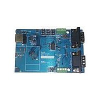
EVAL BOARD FOR XR21V1412IL
Manufacturer
Exar Corporation
Datasheet
1.XR21V1412IL32-F.pdf
(30 pages)
Specifications of XR21V1412IL-0A-EB
Main Purpose
Interface, Transceiver
Embedded
No
Utilized Ic / Part
XR21V1412IL
Interface Type
RS-232, RS-485, USB, UART
Operating Supply Voltage
3.3 V
Product
Interface Modules
Silicon Manufacturer
Exar
Silicon Core Number
XR21V1412
Kit Application Type
Interface
Application Sub Type
UART
Kit Contents
Board
For Use With/related Products
XR21V1412IL32-F
Lead Free Status / RoHS Status
Lead free / RoHS Compliant
Secondary Attributes
-
Primary Attributes
-
Lead Free Status / Rohs Status
Lead free / RoHS Compliant
Other names
1016-1301


REV. 1.1.0
The Device Maximum Power value replaces the bMaxPower field in the USB Standard Configuration
Descriptor. The value specified is in units of 2 mA. For example, the value 0x2F is decimal 47 or 94 mA. Note
that the default bMaxPower of the V1412 device is 94 mA.
The UART Manager enables/disables each UART including the TX and RX FIFOs for each UART. The UART
Manager is located in a separate register block from the 2 UART channels.
There are 2 enhanced UART channels in the V1412. Each UART channel is independent, therefore, they will
need to be initialized and configured independently. Each UART can be configured via USB control transfers
from the USB host. The UART transmitter and receiver sections are described seperately in the following
sections. At power-up, the V1412 will default to 9600 bps, 8 data bits, no parity bit, 1 stop bit, and no flow
control. If a standard CDC driver accesses the V1412, defaults will change.
Driver” on page 7.
The transmitter consists of a 128-byte TX FIFO and a Transmit Shift Register (TSR). Once a bulk-out packet
has been received and the CRC has been validated, the data bytes in that packet are written into the TX FIFO
of the specified UART channel. Data from the TX FIFO is transferred to the TSR when the TSR is idle or has
completed sending the previous data byte. The TSR shifts the data out onto the TX output pin at the data rate
defined by the CLOCK_DIVISOR and TX_CLOCK_MASK registers.
followed by the data bits (starting with the LSB), inserts the proper parity-bit if enabled, and adds the stop-
bit(s). The transmitter can be configured for 7 or 8 data bits with or without parity or 9 data bits without parity.
If 9 bit data is selected without wide mode, the 9th bit will always be ’0’.
When both 9 bit data and wide mode are enabled, two bytes of data must be written. The first byte that is
loaded into the TX FIFO are the first 8 bits (data bits 7-0) of the 9-bit data. Bit-0 of the second byte that is
loaded into the TX FIFO is bit-8 of the 9-bit data. The data that is transmitted on the TX pin is as follows: start
bit, 9-bit data, stop bit. Use the WIDE_MODE register to enable wide mode.
The receiver consists of a 384-byte RX FIFO and a Receive Shift Register (RSR). Data that is received in the
RSR via the RX pin is transferred into the RX FIFO along with any error tags such as Framing, Parity, Break
and Overrun errors. Data from the RX FIFO can be sent to the USB host by sending a bulk-in packet.
If the wide mode is not enabled, then 7 or 8 bits of data and optionally a parity bit are transferred to the USB
host
In wide mode, the V1412 receives a 7, 8 or 9 bit character and then forwards the character along with 3
associated error bits to the USB host in two bytes. If data is 7 or 8 bits, a parity bit is also received and checked
if enabled. If data is 9 bits, no parity is checked. The 9th bit of data is in bit position 0 along with the 3 error bits,
break, frame error and overrun error flags in bit positions 1, 2 & 3 respectively. In wide mode, the parity and
framing error and break flag are associated with the character that they accompany and the overrun error is
tied to the current contents of the entire RX FIFO.
1.4
1.5
1.3.1.4
1.5.1
1.5.1.1
1.5.2
1.5.2.1
Bit 6 is Self-powered mode - set to ’0’ for bus-powered, set to ’1’ for self-powered
Bit 5 is Remote Wakeup support - set to ’0’ for no support, set to ’1’ for remote wakeup support
Bit 4:0 are reserved - set to ’0’
UART Manager
UART
Transmitter
Receiver
Device Maximum Power
Wide Mode Transmit
Wide Mode Receive
9
The transmitter sends the start bit
2-CH FULL-SPEED USB UART
See ”Section 1.2, USB Device
XR21V1412
Related parts for XR21V1412IL-0A-EB
Image
Part Number
Description
Manufacturer
Datasheet
Request
R

Part Number:
Description:
2-ch Full-speed Usb Uart
Manufacturer:
Exar Corporation
Datasheet:
Part Number:
Description:
BiCMOS Fixed, Quad, Voltage Output, Single or Dual Supply 8-Bit Digital-to-Analog Converter
Manufacturer:
Exar Corporation
Datasheet:
Part Number:
Description:
Manufacturer:
Exar Corporation
Datasheet:
Part Number:
Description:
Voltage-Controlled Oscillator
Manufacturer:
Exar Corporation
Datasheet:
Part Number:
Description:
INTEGRATED LINE TRANSMITTER
Manufacturer:
Exar Corporation
Datasheet:
Part Number:
Description:
Monolithic Function Generator
Manufacturer:
Exar Corporation
Datasheet:
Part Number:
Description:
CMOS Microprocessor Compatible Double-Buffered 12-Bit Digital-to-Analog Converter
Manufacturer:
Exar Corporation
Datasheet:
Part Number:
Description:
CMOS 6 BIT HIGH SPEED ANALOG TO DIGITAL CONVERTER
Manufacturer:
Exar Corporation
Datasheet:
Part Number:
Description:
Manufacturer:
Exar Corporation
Datasheet:
Part Number:
Description:
Manufacturer:
Exar Corporation
Datasheet:
Part Number:
Description:
8-Channel, Voltage Output 10 MHz Input Bandwidth 8-Bit Multiplying DACs with Serial Digital Data Por
Manufacturer:
Exar Corporation
Datasheet:
Part Number:
Description:
15 V CMOS Multiplying10-Bit Digital-to-Analog Converter
Manufacturer:
Exar Corporation
Datasheet:
Part Number:
Description:
Monolithic Function Generator
Manufacturer:
Exar Corporation
Datasheet: