RDK-252 Power Integrations, RDK-252 Datasheet - Page 12
RDK-252
Manufacturer Part Number
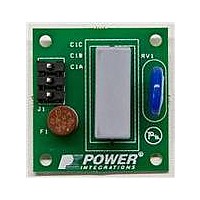
RDK-252
Description
KIT REF DESIGN DG CAPZERO
Manufacturer
Power Integrations
Series
CAPZero™r
Type
Other Power Managementr
Specifications of RDK-252
Main Purpose
Automatic X Capacitor Discharge
Embedded
No
Utilized Ic / Part
CAP014DG, CAP002DG, CAP012DG
Primary Attributes
Low No-Load Input Power (
Secondary Attributes
Surge Testing to EN6100-4-5 Class 4
Input Voltage
85 V to 264 V
Board Size
38.1 mm x 25.4 mm
Product
Power Management Modules
Dimensions
38.1 mm x 25.4 mm
Lead Free Status / RoHS Status
Lead free / RoHS Compliant
For Use With/related Products
CAP014DG
Other names
596-1313
Available stocks
Company
Part Number
Manufacturer
Quantity
Price
Company:

Part Number:
RDK-252
Manufacturer:
Power Integrations
Quantity:
135


Rev. A 030910
In multiple output design NSx, CMSx, AWGSx (where x is the
output number) should also be used.
Step 6 – Selection of TOPSwitch-JX External
Components
CONTROL Pin – External Components
The schematic in Figure 12 shows the external components
required for a typical TOPSwitch-JX power supply design. It is
strongly recommended that a 100 nF capacitor be directly
connected between the CONTROL pin and the SOURCE pin of
the TOPSwitch-JX. This capacitor should be located adjacent
to the TOPSwitch-JX with short traces. In designs using surface
mount components, this capacitor should be located directly at
the pins of the TOPSwitch-JX.
In addition to the 100 nF capacitor connected to the CONTROL
pin, a series combination of a 6.8 W resistor and a 47 µF
electrolytic capacitor is required to be connected between the
CONTROL pin and the SOURCE terminal of the TOPSwitch-JX.
The 47 µF capacitor acts as an energy reservoir and provides
power to the TOPSwitch-JX internal circuitry during start-up and
also provides the timing for auto-restart. Furthermore, this
capacitor together with the dynamic impedance of the CONTROL
pin forms a pole at approximately 160 Hz. A small value resistor
(6.8 W) is generally added in series with this capacitor. This
external resistor, along with the ESR of the CONTROL pin
capacitor (typically about 2 W), provides a stable series resistance
and forms a zero at approximately 400 Hz. Although larger
values of the external resistor may help improve the phase
response, values above 22 W should be avoided.
Step 7 – Selection of Line - Undervoltage / Overvoltage
Components
The line undervoltage detection feature prevents the power
supply from starting until the input voltage is above a defined
level. During power-up or when the switching of the power
MOSFET is disabled during auto-restart, the current into the
V pin must exceed 25 µA to initiate switching (l
As a resistor from the DC rail to the V pin is used to sense the
input voltage, the supply voltage that causes the current into the
V pin to exceed 25 µA defines the undervoltage threshold. The
same resistor also defines the line overvoltage threshold. When
the current into the V pin exceeds I
stops switching, increasing the voltage withstand of the
TOPSwitch-JX to its 725 V BV
With a typical value of 4 MW connected from the DC rail to the
V pin line UV is programmed to 100 VDC and OV to 450 VDC.
The sense resistor should be rated above 400 V, generally
requiring either a single 0.5 W or two 0.25 W devices connected
in series. A typical value of 4 MW is suggested for use as line
sense resistor for universal input applications. Additional
guidance is provided by the design spreadsheet.
If the undervoltage (UV) or the overvoltage (OV) functions are
to be used selectively, a number of circuits are provided in the
TOPSwitch-JX family data sheet to ease the selection of external
components. If the V pin function is not used, the V pin should
12
Application Note
DSS
rating.
OV
(112 µA typical) the device
UV
in data sheet).
Table 6. List of Diodes Suitable for use as the Output Rectifier.
be connected to the SOURCE pin. The V pin should not be left
unconnected.
Step 8 – Selection of Primary Clamp Components
It is recommended that either a Zener clamp or an RCD combined
with a Zener clamp be used in TOPSwitch-JX designs. This is to
ensure that the peak drain voltage is limited to below the BV
of the internal MOSFET while still maximizing efficiency and
minimizing no-load consumption.
A standard RCD clamp designed to limit the peak drain voltage
under peak load conditions represents a significant load as the
output power is reduced, resulting in lower light-load efficiency
and higher no-load consumption.
1N5819
SB140
SB160
MBR160
11DQ06
1N5822
SB340
MBR340
SB360
MBR360
SB540
SB560
MBR745
MBR760
MBR1045
MBR1060
MBR10100
MBR1645
MBR1660
MBR2045CT
MBR2060CT
MBR20100
UF4002
UF4003
MUR120
EGP20D
BYV27-200
UF5401
UF5402
EGP30D
BYV28-200
MUR420
BYW29-200
BYV32-200
Rec. Diode
Schottky
UFR
V
R
(V)
100
100
100
200
200
200
200
100
200
200
200
200
200
200
40
40
60
60
60
40
40
40
60
60
40
60
45
60
45
60
45
60
45
60
20(2×10)
20(2×10)
20(2×10)
I
D
(A)
1.1
7.5
7.5
3.5
10
10
10
16
16
18
1
1
1
1
3
3
3
3
3
5
5
1
1
1
2
2
3
3
3
4
8
Package
TO-220
TO-220
TO-220
TO-220
TO-220
TO-220
TO-220
TO-220
TO-220
TO-220
TO-220
TO-220
TO-220
Axial
Axial
Axial
Axial
Axial
Axial
Axial
Axial
Axial
Axial
Axial
Axial
Axial
Axial
Axial
Axial
Axial
Axial
Axial
Axial
Axial
www.powerint.com
Vishay
Vishay
Vishay
IR
IR
Vishay
Vishay
IR
Vishay
IR
Vishay
Vishay
Vishay / IR
Vishay
Vishay / IR
Vishay
Vishay
Vishay / IR
Vishay
Vishay / IR
Vishay
Vishay / IR
Vishay
Vishay
Vishay
Vishay
Vishay / NXP
Vishay
Vishay
Vishay
Vishay / NXP
Vishay
Vishay / NXP
Vishay / NXP
Manufacturer
AN-47
DSS
Related parts for RDK-252
Image
Part Number
Description
Manufacturer
Datasheet
Request
R

Part Number:
Description:
KIT REF DESIGN TOP HX FOR TOP258
Manufacturer:
Power Integrations
Datasheet:

Part Number:
Description:
KIT REF DESIGN LINKSWITCH 2
Manufacturer:
Power Integrations
Datasheet:

Part Number:
Description:
KIT REF DESIGN 1.2W PS TN FAMILY
Manufacturer:
Power Integrations
Datasheet:

Part Number:
Description:
KIT REF DESIGN 36-72W MOTOR DRVR
Manufacturer:
Power Integrations
Datasheet:

Part Number:
Description:
KIT REF DESIGN FOR LNK457D
Manufacturer:
Power Integrations
Datasheet:

Part Number:
Description:
REFERENCE DESIGN LINKSWITCH-PH
Manufacturer:
Power Integrations
Datasheet:

Part Number:
Description:
Specifications: Manufacturer: Power Integrations ; Output Voltage: 380 VDC ; Input / Supply Voltage (Max): 264 VAC ; Input / Supply Voltage (Min): 90 VAC ; Mounting Style: Through Hole ; Output Current: 0.913 A ; Output Power: 347 W
Manufacturer:
Power Integrations, Inc.

Part Number:
Description:
Power Management Modules & Development Tools TOPSwitch-JX REF. DESIGN KIT
Manufacturer:
Power Integrations
Datasheet:
Part Number:
Description:
Power Management IC Development Tools REF DESIGN RDR-292 PFF LED STREET LIGHT
Manufacturer:
Power Integrations

Part Number:
Description:
KIT REF DESIGN FOR LNK403EG
Manufacturer:
Power Integrations
Datasheet:

Part Number:
Description:
KIT REF DESIGN FOR LNK406EG
Manufacturer:
Power Integrations
Datasheet:

Part Number:
Description:
KIT REF DESIGN LINKSWITCH-CV
Manufacturer:
Power Integrations
Datasheet:

Part Number:
Description:
KIT REF DESIGN PFS762HG
Manufacturer:
Power Integrations
Datasheet:
Part Number:
Description:
Specifications: Family: Eval Boards - DC/DC & AC/DC (Off-Line) SMPS ; Series: HiperLCS™ ; Main Purpose: DC/DC, Step Down ; Outputs and Type: 1, Isolated ; Power - Output: 150W ; Voltage - Output: 24V ; Current - Output: 6.25A ; Voltage - Input:
Manufacturer:
Power Integrations, Inc.
Datasheet:

Part Number:
Description:
KIT REFERENCE DESIGN W/TN376PN
Manufacturer:
Power Integrations
Datasheet: