RDK-252 Power Integrations, RDK-252 Datasheet - Page 21
RDK-252
Manufacturer Part Number
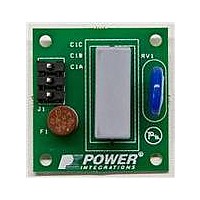
RDK-252
Description
KIT REF DESIGN DG CAPZERO
Manufacturer
Power Integrations
Series
CAPZero™r
Type
Other Power Managementr
Specifications of RDK-252
Main Purpose
Automatic X Capacitor Discharge
Embedded
No
Utilized Ic / Part
CAP014DG, CAP002DG, CAP012DG
Primary Attributes
Low No-Load Input Power (
Secondary Attributes
Surge Testing to EN6100-4-5 Class 4
Input Voltage
85 V to 264 V
Board Size
38.1 mm x 25.4 mm
Product
Power Management Modules
Dimensions
38.1 mm x 25.4 mm
Lead Free Status / RoHS Status
Lead free / RoHS Compliant
For Use With/related Products
CAP014DG
Other names
596-1313
Available stocks
Company
Part Number
Manufacturer
Quantity
Price
Company:

Part Number:
RDK-252
Manufacturer:
Power Integrations
Quantity:
135


Figure 27. No-load Input Power Settling time. (Points Represent Instantaneous
Minimize Output Pre-Loads
Output pre-loads are not required in single output TOPSwitch-JX
designs and may be removed. In multiple output cases a small
pre-load may be required on outputs to which the secondary
side feedback network is not connected. Without a pre-load
these outputs can peak charge significantly above their regulated
voltages. To minimize no-load input power the value of pre-load
resistors should be maximize. For lower dissipation a shunt
regulator can be added to maintain a fixed difference between
the main regulated output and a second output. Here to
minimize losses the transistor of the shunt regulator should be
configured to feed current into the regulated output rather then
to output return.
Include Line Sense Resistor (Connected to V pin)
In addition to providing line undervoltage and overvoltage,
connecting a line sense resistor to the V pin enables the line
feed forward feature. This reduces the amount of current
needed into the device CONTROL pin to program a given duty
cycle as the line voltage is increased. As this current represents
an output load (drawn from both the bias winding via the
optocoupler transistor and output via to optocoupler LED)
reducing the CONTROL pin current also reduces dissipation.
This improves light load efficiency and no-load input power
despite the additional dissipation of the line sense resistor itself.
Clamp Choice and Optimization
For lowest dissipation at light and no-load select either a Zener
or Zener bleed clamp configuration. RCD clamps should be
avoided as the resistor and capacitor value are selected to limit
the peak drain voltage under full load and over-load conditions.
However under light or no-load conditions the capacitor voltage
discharges significantly as both the leakage inductance energy
and switching frequency are lower. As the capacitor has to be
recharged to above the reflected output voltage each switching
cycle the lower capacitor voltage represents wasted energy. It
has the effect of making the clamp dissipation appear as a
significant load just as if it were connected to the output of the
power supply.
www.powerint.com
AN-47
Measurements From Power Meter With No Filtering, Line Represents
Averaged Measurements).
Zener and Zener bleed clamp configurations solve this problem
by preventing the voltage across the capacitor discharging
below a minimum value (defined by the voltage rating of the
Zener) and therefore minimizing clamp dissipation under light
and no-load conditions.
Figure 13 shows recommended clamp configurations. Optimize
the dissipation of the clamp by using the highest value for R
that keeps the peak drain voltage below 675 V under the worst-
case conditions of maximum AC input voltage and output
overload just prior to loss of regulation and entering into auto-
restart. Further information on clamp design is provided in Step
8 of the design flow.
Minimize Bias Winding Voltage Under No-load Conditions
On the primary side the feedback current into the CONTROL
pin is fed from the output of the bias winding. Minimizing the
voltage of the bias winding therefore reduces overall dissipation.
Under no-load and maximum input voltage conditions monitor
the bias winding capacitor voltage with an oscilloscope (C10 in
Figure 31). Reduce the number of bias winding turns on the
transformer until the minimum voltage seen is ≥7 V. Voltages
below this can cause the optocoupler to cut off and results in a
rise in the output voltage at no-load. Due to the integer nature
of the bias winding turns it may not be possible to optimize the
bias voltage perfectly and in this case the value of the bias
capacitor may also be adjusted, increasing the value will
increase the bias voltage slightly. Once optimized verify correct
operation under transient loading conditions to ensure the bias
voltage is always ≥7 V.
Increase Value of Line Sense Resistor
The dissipation of the line sense resistor can be reduced by
adding an additional resistor from the device C to V pin
(Figure 23). Resistor R
CONTROL pin to the VOLTAGE MONITOR pin. This reduces the
current needed from the DC BUS via R
the line UV threshold current of the V pin. This allows the combined
value of R
while still maintaining the same line undervoltage threshold.
Although the line undervoltage (UV) threshold is maintained, the
line overvoltage (OV) threshold voltage is doubled and the line
feed-forward ripple rejection effectiveness reduced. In practice,
for most consumer products, the higher line OV threshold has
little impact due to the low 2 kV differential surge requirement
that class of products has to withstand. This surge level results
in a small increase in the DC bus voltage (filtered by the bulk
capacitor) well below a voltage that could cause the device
BV
For proper operation of the device auto-restart feature a value
<300 kW is required for R
Configure Optocoupler Transistor as Part of Darlington Pair
Configuring the optocoupler as one of the transistors in a
Darlington pair (Figure 24) typically reduces no-load input power
by ≥1 mA × V
the optocoupler LED (feedback) current required to provide a
given CONTROL pin current to maintain output regulation.
DSS
to be exceeded.
LS1
and R
O
. The increased gain of the Darlington reduces
LS2
to be increased from 4 MW to 10 MW
CV
programs a fixed current from the
CV
.
Application Note
LS1
and R
LS2
to exceed
Rev. A 030910
CLAMP
21
Related parts for RDK-252
Image
Part Number
Description
Manufacturer
Datasheet
Request
R

Part Number:
Description:
KIT REF DESIGN TOP HX FOR TOP258
Manufacturer:
Power Integrations
Datasheet:

Part Number:
Description:
KIT REF DESIGN LINKSWITCH 2
Manufacturer:
Power Integrations
Datasheet:

Part Number:
Description:
KIT REF DESIGN 1.2W PS TN FAMILY
Manufacturer:
Power Integrations
Datasheet:

Part Number:
Description:
KIT REF DESIGN 36-72W MOTOR DRVR
Manufacturer:
Power Integrations
Datasheet:

Part Number:
Description:
KIT REF DESIGN FOR LNK457D
Manufacturer:
Power Integrations
Datasheet:

Part Number:
Description:
REFERENCE DESIGN LINKSWITCH-PH
Manufacturer:
Power Integrations
Datasheet:

Part Number:
Description:
Specifications: Manufacturer: Power Integrations ; Output Voltage: 380 VDC ; Input / Supply Voltage (Max): 264 VAC ; Input / Supply Voltage (Min): 90 VAC ; Mounting Style: Through Hole ; Output Current: 0.913 A ; Output Power: 347 W
Manufacturer:
Power Integrations, Inc.

Part Number:
Description:
Power Management Modules & Development Tools TOPSwitch-JX REF. DESIGN KIT
Manufacturer:
Power Integrations
Datasheet:
Part Number:
Description:
Power Management IC Development Tools REF DESIGN RDR-292 PFF LED STREET LIGHT
Manufacturer:
Power Integrations

Part Number:
Description:
KIT REF DESIGN FOR LNK403EG
Manufacturer:
Power Integrations
Datasheet:

Part Number:
Description:
KIT REF DESIGN FOR LNK406EG
Manufacturer:
Power Integrations
Datasheet:

Part Number:
Description:
KIT REF DESIGN LINKSWITCH-CV
Manufacturer:
Power Integrations
Datasheet:

Part Number:
Description:
KIT REF DESIGN PFS762HG
Manufacturer:
Power Integrations
Datasheet:
Part Number:
Description:
Specifications: Family: Eval Boards - DC/DC & AC/DC (Off-Line) SMPS ; Series: HiperLCS™ ; Main Purpose: DC/DC, Step Down ; Outputs and Type: 1, Isolated ; Power - Output: 150W ; Voltage - Output: 24V ; Current - Output: 6.25A ; Voltage - Input:
Manufacturer:
Power Integrations, Inc.
Datasheet:

Part Number:
Description:
KIT REFERENCE DESIGN W/TN376PN
Manufacturer:
Power Integrations
Datasheet: