RDK-252 Power Integrations, RDK-252 Datasheet - Page 29
RDK-252
Manufacturer Part Number
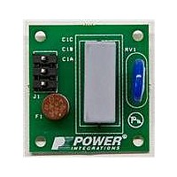
RDK-252
Description
KIT REF DESIGN DG CAPZERO
Manufacturer
Power Integrations
Series
CAPZero™r
Type
Other Power Managementr
Specifications of RDK-252
Main Purpose
Automatic X Capacitor Discharge
Embedded
No
Utilized Ic / Part
CAP014DG, CAP002DG, CAP012DG
Primary Attributes
Low No-Load Input Power (
Secondary Attributes
Surge Testing to EN6100-4-5 Class 4
Input Voltage
85 V to 264 V
Board Size
38.1 mm x 25.4 mm
Product
Power Management Modules
Dimensions
38.1 mm x 25.4 mm
Lead Free Status / RoHS Status
Lead free / RoHS Compliant
For Use With/related Products
CAP014DG
Other names
596-1313
Available stocks
Company
Part Number
Manufacturer
Quantity
Price
Company:

Part Number:
RDK-252
Manufacturer:
Power Integrations
Quantity:
135


Appendix B
Multiple Output Flyback Power Supply Design
The only difference between a multiple output flyback power
supply and a single output flyback power supply of the same
total output power is on the secondary side design.
Design with Lumped Output Power
A simple multiple output flyback design is described in detail in
AN-22, “Designing Multiple Output Flyback Power Supplies with
TOPSwitch.” The design method starts with a single output
equivalent by lumping output power of all outputs to one main
output. Secondary peak current I
derived. Output average current I
lumped power, is also calculated.
Assumption for Simplification
The current waveforms in the individual output windings are
determined by the impedance in each circuit, which is a
function of leakage inductance, rectifier characteristics,
capacitor value and output load. Although this current wave-
form may not be exactly the same from output to output, it is
reasonable to assume that, to the first order, all output currents
have the same shape as for the single output equivalent of
combined circuit.
Output RMS Current vs. Average Current
The output average current is always equal to the DC load current,
while the RMS value is determined by current wave shape.
Since the current wave shapes are assumed to be the same for
all outputs, their ratio of RMS to average currents must also be
identical. Therefore, with the output average current known, the
RMS current for each output winding can be calculated as
www.powerint.com
AN-47
I
SRMS
] g
n
= I
O
] g
n
O
SP
#
, corresponding to the
and RMS current I
I
SRMS
I
O
SRMS
are
where I
output average current of the output, and I
secondary RMS current and output average current for the
lumped single output equivalent design.
Customization of Secondary Designs for Each Output
The turns for each secondary winding are calculated based on
the respective output voltage V
Output rectifier maximum inverse voltage is
With output RMS current I
N
the secondary side design for each output can now be carried
out exactly the same way as for the single output design.
Secondary Winding Wire Size
The TOPSwitch-JX design spreadsheet assumes a CMA of 200
when calculating secondary winding wire diameters. This gives
the minimum wire sizes required for the RMS currents of each
output using separate windings. Designers may wish to use
larger size wire for better thermal performance. Other
considerations, such as skin effect and bobbin coverage, may
suggest the use of a smaller wire by using multiple strands
wound in parallel. In addition, practical considerations in
transformer manufacturing may also dictate the wire size.
S(n)
and output rectifier maximum inverse voltage PIV
SRMS(n)
PIV
and I
N
S
S
] g
] g
n
n
O(n)
= N
= V
are the secondary RMS current and
S
MAX
SRMS(n)
#
# N
V
O(n)
Application Note
, secondary number of turns
O
N
:
] g
V + V
n
S
] g
P
+ V
n
+ V
SRMS
D
D
] g
n
O
and I
] g
n
O
are the
S(n)
Rev. A 030910
known,
29
Related parts for RDK-252
Image
Part Number
Description
Manufacturer
Datasheet
Request
R

Part Number:
Description:
KIT REF DESIGN TOP HX FOR TOP258
Manufacturer:
Power Integrations
Datasheet:

Part Number:
Description:
KIT REF DESIGN LINKSWITCH 2
Manufacturer:
Power Integrations
Datasheet:

Part Number:
Description:
KIT REF DESIGN 1.2W PS TN FAMILY
Manufacturer:
Power Integrations
Datasheet:

Part Number:
Description:
KIT REF DESIGN 36-72W MOTOR DRVR
Manufacturer:
Power Integrations
Datasheet:

Part Number:
Description:
KIT REF DESIGN FOR LNK457D
Manufacturer:
Power Integrations
Datasheet:

Part Number:
Description:
REFERENCE DESIGN LINKSWITCH-PH
Manufacturer:
Power Integrations
Datasheet:

Part Number:
Description:
Specifications: Manufacturer: Power Integrations ; Output Voltage: 380 VDC ; Input / Supply Voltage (Max): 264 VAC ; Input / Supply Voltage (Min): 90 VAC ; Mounting Style: Through Hole ; Output Current: 0.913 A ; Output Power: 347 W
Manufacturer:
Power Integrations, Inc.

Part Number:
Description:
Power Management Modules & Development Tools TOPSwitch-JX REF. DESIGN KIT
Manufacturer:
Power Integrations
Datasheet:
Part Number:
Description:
Power Management IC Development Tools REF DESIGN RDR-292 PFF LED STREET LIGHT
Manufacturer:
Power Integrations

Part Number:
Description:
KIT REF DESIGN FOR LNK403EG
Manufacturer:
Power Integrations
Datasheet:

Part Number:
Description:
KIT REF DESIGN FOR LNK406EG
Manufacturer:
Power Integrations
Datasheet:

Part Number:
Description:
KIT REF DESIGN LINKSWITCH-CV
Manufacturer:
Power Integrations
Datasheet:

Part Number:
Description:
KIT REF DESIGN PFS762HG
Manufacturer:
Power Integrations
Datasheet:
Part Number:
Description:
Specifications: Family: Eval Boards - DC/DC & AC/DC (Off-Line) SMPS ; Series: HiperLCS™ ; Main Purpose: DC/DC, Step Down ; Outputs and Type: 1, Isolated ; Power - Output: 150W ; Voltage - Output: 24V ; Current - Output: 6.25A ; Voltage - Input:
Manufacturer:
Power Integrations, Inc.
Datasheet:

Part Number:
Description:
KIT REFERENCE DESIGN W/TN376PN
Manufacturer:
Power Integrations
Datasheet: