EVAL6229QR STMicroelectronics, EVAL6229QR Datasheet
EVAL6229QR
Specifications of EVAL6229QR


Related parts for EVAL6229QR


EVAL6229QR Summary of contents
Page 1
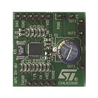
... EVAL6229QR demonstration board using the L6229Q DMOS driver for a three-phase BLDC motor control application Introduction This application note describes the EVAL6229QR demonstration board for the L6229Q DMOS fully integrated three-phase brushless DC motor driver. The board implements a typical application that can be used as a demonstration platform for driving three-phase brushless DC motors with currents ...
Page 2
... Demonstration board description 1 Demonstration board description Table 1. EVAL6229QR pin description Name VS Power supply PGND Ground VDD Power supply H1 Sensor input H2 Sensor input H3 Sensor input SGND Ground DIAG Open-drain output TACHO Open-drain output F/R Logic input EN Logic input/output VREF Analog input BRAKE ...
Page 3
... AN3134 Figure 2. EVAL6229QR demonstration board pin locations The decoding logic integrated in the device is a combinatory logic which provides the appropriate driving signals for the three-phase bridge outputs, based on the signals coming from the three hall sensors H1, H2 and H3. The hall sensors detect rotor position phase BLDC motor ...
Page 4
... Demonstration board description Table 2. EVAL6229QR: electrical specifications (recommended values) Supply voltage range (VS) RMS output current rating (OUTx) Switching frequency Voltage reference range (VREF) Input and enable voltage range Operating temperature range L6229Q thermal resistance junction-to-ambient 4/10 Parameter Doc ID 16960 Rev 1 AN3134 ...
Page 5
... AN3134 Figure 3. EVAL6229QR demonstration board schematic Demonstration board description Doc ID 16960 Rev 1 5/10 ...
Page 6
... R11, R12 and C8 are low-pass filters to provide an external reference voltage through the PWM output of a microcontroller. R9 and C7 are used to set the off-time t can be used to implement a simple frequency-to-voltage converter (speed loop control). Figure 4, Figure 5 the EVAL6229QR demonstration board. A GND area is used for the IC power dissipation. 6/10 Part value 220nF/100V 100µF/63V 10nF/25V 220nF/25V 5 ...
Page 7
... AN3134 Figure 4. EVAL6229QR component placement Figure 5. EVAL6229QR top layer layout Demonstration board description Doc ID 16960 Rev 1 7/10 ...
Page 8
... Demonstration board description Figure 6. EVAL6229QR bottom layer layout 8/10 Doc ID 16960 Rev 1 AN3134 ...
Page 9
AN3134 2 Revision history Table 4. Document revision history Date 13-Apr-2010 Revision 1 Initial release. Doc ID 16960 Rev 1 Revision history Changes 9/10 ...
Page 10
... Information in this document is provided solely in connection with ST products. STMicroelectronics NV and its subsidiaries (“ST”) reserve the right to make changes, corrections, modifications or improvements, to this document, and the products and services described herein at any time, without notice. All ST products are sold pursuant to ST’s terms and conditions of sale. ...