78M6612-DB/OMU-RF Maxim Integrated Products, 78M6612-DB/OMU-RF Datasheet - Page 10
78M6612-DB/OMU-RF
Manufacturer Part Number
78M6612-DB/OMU-RF
Description
KIT DEMO OUTLET MEAS OMU1-S-RF
Manufacturer
Maxim Integrated Products
Datasheets
1.78M6612-IMF.pdf
(111 pages)
2.78M6612-EVM-1.pdf
(58 pages)
3.78M6612-DBOMU-RF.pdf
(41 pages)
4.78M6612-DBOMU-USB.pdf
(4 pages)
Specifications of 78M6612-DB/OMU-RF
Main Purpose
*
Embedded
*
Utilized Ic / Part
*
Primary Attributes
*
Secondary Attributes
*
Processor To Be Evaluated
78M6612
Data Bus Width
8 bit
Interface Type
UART
Lead Free Status / RoHS Status
Lead free / RoHS Compliant


78M6612 OMU1-S-RF Demo Unit User Manual
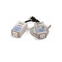
2.2.2 Attaching the UART-ISO Daughter Board to the OMU1-S-RF
Attach the UART-ISO daughter board to the OMU1-S-RF for use with external development boards.
External development boards are customer-supplied hardware incorporating their communications
module and debug interfaces. Their debug interfaces are typically RS-232 or USB cables with direct
connections to a PC. The daughter board incorporates signal isolators to protect the external
development board hardware and its attached PC.
Attach the UART-ISO daughter board to the OMU1-S-RF’s UART cable as shown. Take note of the
cable’s
The UART-ISO daughter board does not supply power to the attached external development board. The
female connector J2 is provided for attaching the external development board. The J2 pin assignments
are as follows:
The UART-ISO daughter board does not support 1.8V signal levels.
10
Red
Pin 1
Pin 2
Pin 3
Pin 4
Do not attach external equipment to the OMU1-S-RF when using the UART-ISO.
If it is necessary to attach test equipment, contact Teridian for instructions.
wire (+V) with regards to the daughter board’s connector pin assignments.
+3.3V or +5V (input, required to power signal isolator)
TX (78M6612 output, Vout dependent on voltage at pin 1)
RX (78M6612 input, Vin threshold dependent on voltage at pin 1)
GND
UM_6612_016
Rev. 1.2
Related parts for 78M6612-DB/OMU-RF
Image
Part Number
Description
Manufacturer
Datasheet
Request
R

Part Number:
Description:
KIT DEMO OUTLET MEASUREMENT OMU1
Manufacturer:
Maxim Integrated Products
Datasheet:

Part Number:
Description:
IC POWER MEASUREMENT AC 68-QFN
Manufacturer:
Maxim Integrated Products
Datasheet:

Part Number:
Description:
The Teridian™ 78M6612 is a highly integrated, single-phase, power and energy measurement and monitoring system-on-chip (SoC) that includes a 32-bit compute engine (CE), an MPU core, RTC, and flash
Manufacturer:
Maxim
Datasheet:

Part Number:
Description:
IC POWER MEASUREMENT AC 64-LQFP
Manufacturer:
Maxim Integrated Products
Datasheet:
Part Number:
Description:
IC POWER MEASUREMENT AC 68-QFN
Manufacturer:
Maxim Integrated Products
Datasheet:

Part Number:
Description:
IC POWER MEASUREMENT AC 64-LQFP
Manufacturer:
Maxim Integrated Products
Datasheet:
Part Number:
Description:
Current & Power Monitors & Regulators
Manufacturer:
Maxim Integrated Products
Datasheet:
Part Number:
Description:
Current & Power Monitors & Regulators 2 Out Sgl Phase Pwr & Energy Msrmt IC
Manufacturer:
Maxim Integrated Products
Datasheet:
Part Number:
Description:
Current & Power Monitors & Regulators
Manufacturer:
Maxim Integrated Products
Datasheet:
Part Number:
Description:
Current & Power Monitors & Regulators
Manufacturer:
Maxim Integrated Products
Datasheet:
Part Number:
Description:
Current & Power Monitors & Regulators
Manufacturer:
Maxim Integrated Products
Datasheet:
Part Number:
Description:
Current & Power Monitors & Regulators 2 Out Sgl Phase Pwr & Energy Msrmt IC
Manufacturer:
Maxim Integrated Products
Datasheet:
Part Number:
Description:
Current & Power Monitors & Regulators
Manufacturer:
Maxim Integrated Products
Datasheet:
Part Number:
Description:
Current & Power Monitors & Regulators
Manufacturer:
Maxim Integrated Products
Datasheet:
Part Number:
Description:
Current & Power Monitors & Regulators 2 Out Sgl Phase Pwr & Energy Msrmt IC
Manufacturer:
Maxim Integrated Products
Datasheet: