78M6612-DB/OMU-USB Maxim Integrated Products, 78M6612-DB/OMU-USB Datasheet
78M6612-DB/OMU-USB
Specifications of 78M6612-DB/OMU-USB


Related parts for 78M6612-DB/OMU-USB


78M6612-DB/OMU-USB Summary of contents
Page 1
TM Simplifying System Integration OMU1-S-WW Demo Unit User Manual November 6, 2009 Rev. 1.0 UM_6612_012 ...
Page 2
OMU1-S-WW Demo Unit User Manual © 2009 Teridian Semiconductor Corporation. All rights reserved. Teridian Semiconductor Corporation is a registered trademark of Teridian Semiconductor Corporation. Simplifying System Integration is a trademark of Teridian Semiconductor Corporation. Microsoft, Windows, Vista, and Excel are ...
Page 3
UM_6612_012 1 Introduction ................................................................................................................................... 5 1.1 Package Contents ................................................................................................................ 5 1.2 System Requirements ........................................................................................................... 5 1.3 Safety and ESD Notes .......................................................................................................... 5 1.4 Firmware Demo Code Introduction ........................................................................................ 6 1.5 Testing the Demo Unit Prior to Shipping ................................................................................ 6 2 ...
Page 4
OMU1-S-WW Demo Unit User Manual Figures Figure 1: Example OMU1 Connections .................................................................................................... 9 Figure 2: HyperTerminal Window with the Disconnect Button ................................................................. 11 Tables Table 1: COM Port Setup Parameters .................................................................................................... 10 4 UM_6612_012 Rev. 1.0 ...
Page 5
... The 78M6612 IC monitors the AC line voltages and load current. The embedded demo firmware calculates the RMS line voltage and RMS load current, Watts, VA, VAR and power factor for a single outlet. Access to real-time data in the 78M6612 is available via a serial interface using a Command Line Interface (CLI). A USB interface on the OMU1-S-WW provides the serial connection and DC power to the 78M6612 ...
Page 6
... For information about the CLI, see the 6612_OMU_S2_URT_V1_13 Firmware Description Document. The OMU1 Demo Unit is shipped with Demo Code Revision 1.13 or later loaded in the 78M6612 chip and included on the CD. The code revision can be verified by entering the command >i via the command line interface. Firmware for the Demo Unit can be updated using either the Teridian TFP1 or an in-circuit emulator such as the Signum Systems™ ...
Page 7
UM_6612_012 2 Installation 2.1 USB Driver Installation The OMU1-S-WW module contains an optically isolated USB interface for serial communications with a PC. The FTDI USB controller IC FT232RL performs the USB functions. The FTDI Windows driver presents a virtual COM ...
Page 8
OMU1-S-WW Demo Unit User Manual 2.2 Confirm COM Port Mapping 1. Launch the Control Panel and click on the System icon. 2. The System Properties screen appears. Click on the Hardware tab. Click on Device Manager. Under Ports (COM & ...
Page 9
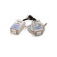
UM_6612_012 2.3 Basic Connection Setup Figure 1 shows the basic connections of the OMU1-S-WW with the external equipment. The OMU1-S-WW is powered through the USB cable that is connected to the host PC. This same USB cable provides the communications ...
Page 10
... HyperTerminal can be found in Windows by selecting Start All Programs Accessories Communications HyperTerminal. The connection parameters are configured by selecting File Properties. The New Connection Properties menu appears. Select the appropriate COM port and click Configure. The COMn Properties menu appears. 10 Table 1: COM Port Setup Parameters 78M6612 38400 8 None 1 Xon/Xoff ...
Page 11
UM_6612_012 Note that port parameters can only be adjusted when the connection is not active. It may be necessary to click the Disconnect Button (shown in Disconnect Figure 2: HyperTerminal Window with the Disconnect Button Rev. 1.0 OMU1-S-WW Demo Unit ...
Page 12
OMU1-S-WW Demo Unit User Manual 2.5 NI™ RunTime Installation The GUI Dashboard program is created using National Instruments LabVIEW™. The NI RunTime Engine must be installed first before launching the Dashboard GUI. 1. Open the LabWindows XP Installer directory on ...
Page 13
UM_6612_012 3. Select the destination directory. 4. Accept the License Agreement. Rev. 1.0 OMU1-S-WW Demo Unit User Manual 13 ...
Page 14
OMU1-S-WW Demo Unit User Manual 5. Start the installation. 6. When the installation is complete, restart your computer. 14 UM_6612_012 Rev. 1.0 ...
Page 15
UM_6612_012 2.6 Install LabWindows™ XP Pro Update Do not install LabWindows XP Pro Update on Win2k. 1. Launch the LabWindows XP Pro VISA Update.exe installation file on the CD. 2. Un-zip the file to the proper folder. Rev. 1.0 OMU1-S-WW ...
Page 16
OMU1-S-WW Demo Unit User Manual 3. Start the installation. 4. Select the proper destination directories. 5. Accept the License Agreements. 16 UM_6612_012 Rev. 1.0 ...
Page 17
UM_6612_012 6. The following screen appears. Click Next. 7. Click Finish. 8. Copy the OMU GUI V2p1.exe application file from the CD to your PC. 9. Restart your computer. Rev. 1.0 OMU1-S-WW Demo Unit User Manual 17 ...
Page 18
OMU1-S-WW Demo Unit User Manual 3 Operating the Dashboard GUI Start the Dashboard Program using Teridian OMU GUI V2p1.exe. 3.1 Port Selection The COM port must be selected before data can be received from the OMU1-S-WW. Select the appropriate COM ...
Page 19
UM_6612_012 3.2 Creating a Measurement Data Log File Upon clicking the Run button, a File Write dialog box appears. The GUI stores retrieved measurement data to a file for post processing. Enter the desired subdirectory and file name. Click OK ...
Page 20
OMU1-S-WW Demo Unit User Manual 3.4 Selecting the Display Scales The range of values displayed in the Watts dial, the Current (rms) dial, and the Voltage (rms) dial can be changed. Use the Voltage Range, Watts Range and Current Range ...
Page 21
UM_6612_012 3.6 Begin Tracking Minimum and Maximum Conditions To begin tracking minimum and maximum conditions as they occur, click the Start Min/Max button. Minimum values will display in the second row and maximum values will display in the third row. ...
Page 22
OMU1-S-WW Demo Unit User Manual 3.8 Selecting Wide Band or Narrow Band Measurement The GUI provides for two measurement algorithm options. The Wide Band measurement method is optimal for measuring power from equipment with switching power supplies. The Narrow Band ...
Page 23
UM_6612_012 3.11 Neutral Voltage Alarm The Neutral Voltage Alarm turns red when the Line and Neutral wires are reversed and Earth GND is connected. Earth GND must be connected for this function to operate properly. Line Earth GND 3.12 Line ...
Page 24
OMU1-S-WW Demo Unit User Manual 3.13 Accumulated Energy Usage and Expense Tracking If a Cost per KWh value is entered, the OMU1-S-WW will calculate and display the accumulated energy cost. • Slide the vertical scroll bar down to display the ...
Page 25
UM_6612_012 3.15 Using the Parameter Graph Use the Parameter Graph to display sample size averages for a specified parameter and time scale. • Select the parameter to chart using the Select Parameter menu. • Select the time scale using the ...
Page 26
OMU1-S-WW Demo Unit User Manual • Below the Alarm Status Indicators are the current threshold values and data entry boxes to change the OMU1 event counter threshold values. • Enter a new value and click on the respective Write button ...
Page 27
UM_6612_012 3.18 Log File Import to Excel The OMU1-S-WW measurement data can be graphed and post processed by importing its text data into various analysis programs. The column data is separated by commas. The first dozen lines contain OMU1-S-WW informational ...
Page 28
OMU1-S-WW Demo Unit User Manual Change the Files of type to all Files(*.*). Then find your sub-directory and select your data log file. No changes required on the next dialog box, click Next. Uncheck Tab and then check Comma. Click ...
Page 29
UM_6612_012 Select Text for Column data format. Click Finish to complete importing log file data. The log file text data can now be parsed using standard Excel formulas. Rev. 1.0 OMU1-S-WW Demo Unit User Manual 29 ...
Page 30
... For more information about Teridian Semiconductor products or to check the availability of the 78M6612 OMU1 Demo Unit, contact us at: http://www.teridian.com/contact-us/ 6440 Oak Canyon Road Suite 100 Irvine, CA 92618-5201 Telephone: (714) 508-8800 FAX: (714) 508-8878 Revision History Revision Date Description 1.0 11/6/2009 First publication. 30 UM_6612_012 Order Number 78M6612-DB/OMU-USB Rev. 1.0 ...