101-1268 Rabbit Semiconductor, 101-1268 Datasheet - Page 47
101-1268
Manufacturer Part Number
101-1268
Description
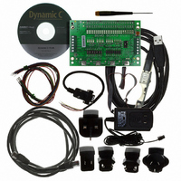
KIT FOR BL4S100 STARTER PACKAGE
Manufacturer
Rabbit Semiconductor
Type
Single Board Computers (SBC)r
Datasheet
1.20-101-1258.pdf
(144 pages)
Specifications of 101-1268
Product
Modules
Processor Type
BL4S100
Sram
512 KB
Timers
8 bit, 10 bit
Number Of I/os
20
Backup Battery
3 V Lithium Coin Type
Operating Voltage
9 V to 36 V
Power Consumption
2 W
Board Size
96 mm x 146 mm x 16 mm
Description/function
Computer Module
For Use With/related Products
BL4S100
Lead Free Status / RoHS Status
Not applicable / Not applicable
Other names
316-1157


4.2.3 A/D Converter Inputs
The following sample programs are found in the
You will need a separate power supply and a multimeter to use with these sample programs.
•
•
•
•
BL4S100 User’s Manual
ADC_CAL_DIFF.C
channel using two measured voltages to generate two coefficients, gain and offset,
which are rewritten into the user block. The voltage that is being monitored is displayed
continuously.
Once you compile and run this sample program, connect the power supply across a
differential channel pair, then follow the instructions in the Dynamic C
ADC_CAL_MA.C
using two measured currents to generate two coefficients, gain and offset, which are
rewritten into the reserved user block. The current that is being monitored is displayed
continuously.
Before you compile and run this sample program, jumper pins 1–2 and 5–6 on headers
J10 and J11. Then connect a current meter in series with the power supply connected to
one of pins AIN0–AIN3 and AGND, then compile and run the sample program, and
follow the instructions in the Dynamic C
ADC_CAL_SE_UNIPOLAR.C
A/D converter channel using two measured voltages to generate two coefficients, gain
and offset, which are rewritten into the reserved user block. The voltage that is being
monitored is displayed continuously.
Before you compile and run this sample program, connect the power supply (which
should be OFF) between the pin (AIN0–AIN7) of the channel you are calibrating and
AGND, then compile and run the sample program, and follow the instructions in the
Dynamic C
ADC_AVERAGING_SE_UNIPOLAR.C
age voltage of each of the single-ended analog input channels using a sliding window.
The voltage is calculated from coefficients read from the display—the two calibration
coefficients, gain and offset, in the Dynamic C
mode of operation.
Before you compile and run this sample program, connect the power supply (which
should be OFF) between the pin (AIN0–AIN7) of an analog input channel and AGND,
then compile and run the sample program, and follow the instructions in the Dynamic C
STDIO
NOTE: The calibration sample programs will overwrite the calibration constants set at
NOTE: For best results use a multimeter with a resolution of at least 4½ digits.
the factory. Before you run these sample programs, run USERBLOCK_READ_
WRITE.C in the SAMPLES\UserBlock folder to save the factory calibration con-
stants in case you inadvertently write over them while running other sample programs.
window.
STDIO
—Demonstrates how to recalibrate a milli-amp A/D converter channel
—Demonstrates how to recalibrate a differential A/D converter
window.
—Demonstrates how to recalibrate a single-ended unipolar
—Demonstrates how to read and display the aver-
STDIO
SAMPLES\BL4S1xx\ADC
STDIO
window.
window for each channel, and
STDIO
subdirectory.
window.
45
Related parts for 101-1268
Image
Part Number
Description
Manufacturer
Datasheet
Request
R

Part Number:
Description:
COMPUTER SNGLBD BL2120 FRCTNLOCK
Manufacturer:
Rabbit Semiconductor
Datasheet:

Part Number:
Description:
KIT APPLCTN RABBITCORE RCM4010
Manufacturer:
Rabbit Semiconductor
Datasheet:

Part Number:
Description:
KIT MESH NETWORK ADD-ON RCM4510W
Manufacturer:
Rabbit Semiconductor
Datasheet:

Part Number:
Description:
KIT DEV FOR BL2500 COYOTE
Manufacturer:
Rabbit Semiconductor
Datasheet:

Part Number:
Description:
KIT APPLICATION SIMPLE SENSOR
Manufacturer:
Rabbit Semiconductor
Datasheet:

Part Number:
Description:
KIT DEV RCM5400W US/INTERNATIONL
Manufacturer:
Rabbit Semiconductor
Datasheet:

Part Number:
Description:
DEV KIT DELUXE MINICORE RCM5600W
Manufacturer:
Rabbit Semiconductor
Datasheet:


Part Number:
Description:
DEV KIT STANDARD MINI RCM5600W
Manufacturer:
Rabbit Semiconductor
Datasheet:

Part Number:
Description:
MODULE RABBITCORE RCM3720
Manufacturer:
Rabbit Semiconductor
Datasheet:
Part Number:
Description:
MODULE RABBITCORE RCM3220
Manufacturer:
Rabbit Semiconductor
Datasheet:
Part Number:
Description:
MODULE RABBITCORE RCM3210
Manufacturer:
Rabbit Semiconductor
Datasheet:
Part Number:
Description:
COMPUTER SGL-BOARD OP6600 W/SRAM
Manufacturer:
Rabbit Semiconductor
Datasheet:
Part Number:
Description:
COMPUTER SGL-BD BL2000 SRAM/FLSH
Manufacturer:
Rabbit Semiconductor