DM303006 Microchip Technology, DM303006 Datasheet
DM303006
Specifications of DM303006


Related parts for DM303006

DM303006 Summary of contents
Page 1
... 2001 Microchip Technology Inc. ® EVALUATION KIT II INCLUDES: • About the • Installing • Evaluation Kit II GUI Software • Monitoring • Encoders EE OQ • Demonstrating Transmitters • The Main Board • Appendix A: Schematic Diagrams • Appendix B: In-Circuit Programming • Appendix C: HCS500 Support • ...
Page 2
... Microchip Technology Incorporated in the U.S.A. All other trademarks mentioned herein are property of their respective companies. © 2001, Microchip Technology Incorporated, Printed in the U.S.A., All Rights Reserved. Microchip received QS-9000 quality system certification for its worldwide headquarters, design and wafer fabrication facilities in Chandler and Tempe, Arizona in July 1999. The Company’ ...
Page 3
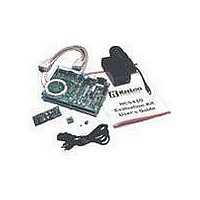
... Programmer and Decoder Demonstration Board • Two Demo K Transmitter Boards EELOQ • K Secure Data Product CD-ROM EELOQ • Sample Kit containing various and decoder samples 2001 Microchip Technology Inc. ® L Evaluation Kit The K EELOQ • All • ...
Page 4
... COM1 but can be changed in the Port” dialog played by selecting “Com Port” from the “Options” menu. ® EVALUATION KIT USER’S GUIDE software uses a serial port to communi- “Com box (Figure 2-1). The dialog box is dis- 2001 Microchip Technology Inc. ...
Page 5
... The two version numbers most probably will differ as new firmware and software revisions will be released to improve or add support for new devices and features. 2001 Microchip Technology Inc. ® EVALUATION KIT II USER’S GUIDE ...
Page 6
... Key used for Authentication (IFF) will match both the Key Generation Algorithm (Simple Learn in this case) and the Reader’s Manufacturers Code ( in this example, the value FEDCBA9876543210 Project configuration file Decoder Block 2001 Microchip Technology Inc. EVALUATION KIT II USER’S GUIDE ). HEX ). HEX ...
Page 7
... The device selection dialog boxes show lists of avail- able and supported models to choose from. One of the many distinguishing characteristics of each device is indicated: HCS301 operating voltage, HCS201’s adjustable internal oscillator and HCS473 three-axis transponder. 2001 Microchip Technology Inc. ® EVALUATION KIT II USER’S GUIDE EE ...
Page 8
... Hitting the DELETE (DEL) key or selecting the Edit- >Delete function from the main menu removes the selected block from the project window. A dialog box will pop-up asking to confirm the operation before the actual deletion. DS41155A-page 6 Software Decoders Custom Decoder 2001 Microchip Technology Inc. ...
Page 9
... A user may wish to define a decoder component derived from Application Note software or other Cus- tom Code developed to fulfill a requirement no existing decoder could. A Manchester reception based decoder using a 40-pin PIC16F77 FLASH microcon- troller, for example. 2001 Microchip Technology Inc. ® EVALUATION KIT II USER’S GUIDE EE OQ ...
Page 10
... Project. Based on cus- tom software, the only means of configuring such devices is by changing source code, re-assembling it ® and programming a new PICmicro (MCU) using a standard Microchip programmer like a PICSTART Plus or a PRO MATE II. DS41155A-page 8 - PIC16F77”, Tran- EELOQ microcontroller 2001 Microchip Technology Inc. ...
Page 11
... The “Program Mode” button will reflect this state by changing its caption to “Program”. Subse- quent button activations will now perform the actual programming attempts. Failure, success, or any serial communication error will be reported on the status line. 2001 Microchip Technology Inc. ® EVALUATION KIT II USER’S GUIDE EE OQ Pressing the “ ...
Page 12
... The “Program Mode” button will reflect this state by changing its caption to “Program”. Subse- quent button activations will now perform the actual programming attempts. Failure, success or any serial communication error will be reported on the status line. 2001 Microchip Technology Inc. HCS500 ...
Page 13
... Encoder model. Several Check Boxes to enable and disable various feature like a Start Pulse or a Minimum number of Code Words per transmission The standard Status line to communicate success and/or Failure of a Programming attempt. 2001 Microchip Technology Inc. ® EVALUATION KIT II USER’S GUIDE EE ...
Page 14
... Notepad or any Text Editing program and then printed, e-mailed or faxed for documentation or support pur- poses. Note: The user is recommended not to edit the configuration file contents by hand since this could lead to unexpected results when the Evaluation Kit II GUI Software re-loads the project. 2001 Microchip Technology Inc. ...
Page 15
... Hopping code and Fixed code fields appropriately and reproduces an oscilloscope-like waveform display for demonstration purposes. FIGURE 4-1: THE RADIO TRANSMISSION MONITOR DIALOG BOX Hopping code Status A36FC5DD 2001 Microchip Technology Inc ® L Transmissions EE OQ The initial firmware and software release (rev ...
Page 16
... Check that the RS-232 cable between the main board and place. 3. Check that the JP1 jumper on the main board is in place. 4. Check that the link JP1 on the Demo Transmitter board is in place. 2001 Microchip Technology Inc. ...
Page 17
... EE OQ consult the related data sheets included in the CD ROM or download them from the Microchip web site: http:\\www.microchip.com. A brief summary of basic encoder features is given in Table 5-1. 2001 Microchip Technology Inc. K ® Encoders EE OQ Minimal external components are required to imple- ment a complete remote transmitter ...
Page 18
... This prevents the encoder from draining the battery if a button is acciden- tally pressed while in a pocket or purse. The time-out period is typically 25 seconds but some devices have shorter or programmable time-out periods essential for certification in some countries. L encod 2001 Microchip Technology Inc. ...
Page 19
... HCS360 X X HCS361 X — HCS362 X X HCS365 X X HCS370 X X HCS410 X X HCS412 X X HCS473 X X 2001 Microchip Technology Inc. ® EVALUATION KIT II USER’S GUIDE ENCODER DIFFERENCES OQ Overflow Function 13V Bits Inputs — X — 3 — X — 3 — X — ...
Page 20
... RF transmitter modulator circuit input. removed, it can be used to monitor the digital encoder output while the RF section is disabled. LED control jumper LED pin 1 Encoder socket Lithium battery fits 8- and 14-pin ® EVALUATION KIT II USER’S GUIDE If RF output jumper 2001 Microchip Technology Inc. ...
Page 21
... Although the kit’s included Demonstra- tion Transmitters connect multiple lines ( out of 16 available) to the Pro- gramming Connector, only four lines are typically required for production In-Circuit Serial Programming (ICSP). 2001 Microchip Technology Inc. ® EVALUATION KIT II USER’S GUIDE EE ...
Page 22
... Prototyping Area FIGURE 7-1: THE MAIN BOARD Serial Interface Step Up Circuit Demo Decoders DS41155A-page 20 K The Main Board Power Supply Radio Receiver Programming Socket ® L EVALUATION KIT USER’S GUIDE Transponder Interface Main Processor Prototyping Area 2001 Microchip Technology Inc. ...
Page 23
... Main Processor with separate pairs of clock and data lines such that they may be independently config- ured. Although the current firmware release does not support it, the decoder coprocessor functionality could be demonstrated. 2001 Microchip Technology Inc. ® EVALUATION KIT II USER’S GUIDE ...
Page 24
... The Manufacturer’s Key for the Software Decoder sam- ples is by default set to 0123456789ABCDEF Since the software decoders are based on OTP micro- controllers (PIC16C54 and PIC16C56) they cannot be configured by the Evaluation Kit software. 2001 Microchip Technology Inc. and its different EELOQ . 16 ...
Page 25
... The entry will be recorded in the project configura- tion file for documentation purposes. • change the Manufacturer Code used for the Key Generation process during Learning • select the desired learning scheme among: 2001 Microchip Technology Inc. ® EVALUATION KIT II USER’S GUIDE ...
Page 26
... VLOW – The output is activated when the V set in a transmission when the battery supply voltage drops below the prede- termined threshold. Maximum FUNC OK VLOW Transmitters — — — — 6 — — — bit is LOW L encoder sets this bit EE OQ 2001 Microchip Technology Inc. ...
Page 27
... S0 – S3. The Evaluation Kit II software and PRO MATE II soft- ware (Microchip Universal Programmer) have been designed so that the Encoder Key Generation phase is transparent to the user. 2001 Microchip Technology Inc. ® EVALUATION KIT II USER’S GUIDE ...
Page 28
... HCS512 decoder’s separate reset line. The BOOT button is used by the BOOT loader to down- load new firmware into the Main Processor from the Serial Port and bootstrap it into execution. Socket for 24LCXX 20 MHz Crystal Reset 2001 Microchip Technology Inc. ...
Page 29
... The user must guarantee that the Prototype area cus- tom circuit current draw added to the Main Board con- sumption (varying with the number of decoders mounted and their use) does not exceed the 100 mA total limit. 2001 Microchip Technology Inc. ® EVALUATION KIT II USER’S GUIDE ...
Page 30
... RC1), while a fil- tered and amplified Read signal is received on the standard RE1 I/O pin. A Write signal (pin RB0), can also control the resonant circuit through a MOSFET driver. reader coil connector (JP2) 2001 Microchip Technology Inc. ...
Page 31
... The socket only allows the insertion of encoder DIP samples in 8-, 14- and 20-pin packages. The 20-pin capability provides for future compatibility. Special third party adaptors may be purchased converting the DIP interface to another desired package. 2001 Microchip Technology Inc. ® EVALUATION KIT II USER’S GUIDE ...
Page 32
... K L EVALUATION KIT II USER’S GUIDE EE OQ FIGURE 7-12: IN-CIRCUIT PROGRAMMING OF A DEMO TRANSMITTER insert flip backside up DS41155A-page 30 back side 2001 Microchip Technology Inc. ...
Page 33
... M Appendix A: Schematic Diagrams FIGURE A-1: ENCODER SCHEMATIC 2001 Microchip Technology Inc. ® EVALUATION KIT USER’S GUIDE DS41155A-page 31 ...
Page 34
... K L EVALUATION KIT II USER’S GUIDE EE OQ FIGURE A-2: MAIN BOARD SCHEMATIC DS41155A-page 32 2001 Microchip Technology Inc. ...
Page 35
... FIGURE A- DECODER SCHEMATIC EE OQ 2001 Microchip Technology Inc. ® EVALUATION KIT II USER’S GUIDE EE OQ DS41155A-page 33 ...
Page 36
... K L EVALUATION KIT II USER’S GUIDE EE OQ FIGURE A-4: TRANSPONDER READER & STEP UP CIRCUIT DS41155A-page 34 2001 Microchip Technology Inc. ...
Page 37
... These devices can be programmed In-Circuit using the Demo Transmitter (directly inserted in connector J6 providing custom In-Circuit described in the following table: TABLE B-1: HCS101/HCS200/HCS201/HCS300/HCS301/HCS320 ICSP J3 Pin Description 1 GND 11 CLOCK 3 DATA 14 Prog 2001 Microchip Technology Inc GND TX_232 DATA RX_232 515_DATA Prog 515_CLK NC 512_DAT Prog 512_CLK S1 +5V RFIN ...
Page 38
... TABLE B-3: HCS362/HCS410/HCS412 ICSP J3 Pin Description 1 GND 11 CLOCK 3 DATA 14 Prog B.4 HCS365/HCS370/HCS473 ICSP Connection These devices can not be programmed In-Circuit using the Demo Transmitter. DS41155A-page 36 as Encoder Pin Description 5 GND DATA Encoder Pin Description 5 GND DATA 2001 Microchip Technology Inc. ...
Page 39
... The HCS500 must be connected to the companion 24LC01 (or 24LC02) memory and both parts must be powered. Note: Refer to Appendix C for a description of the modifications required to the Main Board to provide direct support for this decoder. 2001 Microchip Technology Inc. ® EVALUATION KIT II USER’S GUIDE EE OQ Encoder Pin ...
Page 40
... Circuit using the connections described in the following table: TABLE B-7: HCS500 ICSP J3 Pin Description 1 GND 8 CLK_515 6 DAT_515 The HCS515 decoder target board must be powered 5V) DD DS41155A-page 38 Decoder Pin Description 5 GND 12 CLOCK 13 DATA 4 MCLR Decoder Pin Description 12 GND 10 CLOCK 9 DATA 2001 Microchip Technology Inc. ...
Page 41
... Step 1. Remove the 14-pin DIP socket. Be extremely careful not to break any PCB connection. Step 2. Insert two 8-pin DIP sockets starting from pin 1 (squared) on the left and leaving the last row empty as illustrated in . 2001 Microchip Technology Inc HCS515 socket ® L EVALUATION KIT OQ II USER’ ...
Page 42
... Step 4. Insert R65 (4.7 KΩ SMD resistor). FIGURE C-3: RESISTORS R64, R65, R66 POSITION Note: After the modifications, the LEARN OUT LED assumes the functionality of the HCS500 decoder’s single output. DS41155A-page 40 HCS515 HCS515 socket HCS500+NVM socket HCS500 NC pin 1 2001 Microchip Technology Inc. ...
Page 43
... J5-ICSP J4-ICD Programming Socket D.1.4 J2- RS-232 (9-PIN) Pin Hardware handshake is not used in revision (v.3.00.00) of the firmware ® L EVALUATION KIT USER’S GUIDE Signal MCU pin NC — TX RC6 RX RC7 NC — GND — CTS RC5 RTS RC0 NC — 2001 Microchip Technology Inc. ...
Page 44
... MCLR 2 +5V 3 GND 4 DAT_ICSP 5 CLK_ICSP DS41155A-page 42 Pin Signal MCU pin 2 TX_232 RC6 4 RX_232 RC7 6 515_DATA RE2 8 515_CLK RA3 10 512_DAT RA2 12 512_CLK RA1 14 + RFIN RE0 MCU pin MCLR RB7 RB6 RB3 MCU pin MCLR RB7 RB6 RB3 2001 Microchip Technology Inc. ...
Page 45
... The inductance of the coil has to match the capacitance value for resonance at 125 kHz. Other frequencies can be obtained by changing the PWM output frequency of the PIC16F877, but will require also the optimization of the input filter. 2001 Microchip Technology Inc. ® EVALUATION KIT II USER’S GUIDE ...
Page 46
... K L EVALUATION KIT II USER’S GUIDE EE OQ NOTES: DS41155A-page 44 2001 Microchip Technology Inc. ...
Page 47
... NOTES: 2001 Microchip Technology Inc. ® EVALUATION KIT II USER’S GUIDE EE OQ DS41155A-page 47 ...
Page 48
... Korea Microchip Technology Korea 168-1, Youngbo Bldg. 3 Floor Samsung-Dong, Kangnam-Ku Seoul, Korea 135-882 Tel: 82-2-554-7200 Fax: 82-2-558-5934 Singapore Microchip Technology Singapore Pte Ltd. 200 Middle Road #07-02 Prime Centre Singapore, 188980 Tel: 65-334-8870 Fax: 65-334-8850 Taiwan Microchip Technology Taiwan 11F-3, No. 207 ...