DM303006 Microchip Technology, DM303006 Datasheet - Page 30
DM303006
Manufacturer Part Number
DM303006
Description
KIT EVALUATION KEELOQ
Manufacturer
Microchip Technology
Series
KEELOQ®r
Type
KeeLoq®r
Specifications of DM303006
Silicon Manufacturer
Microchip
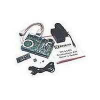
Kit Contents
Main Board, 2 Transmitters, Cables And Power Supply
Tool / Board Applications
General Purpose MCU, MPU, DSP, DSC
For Use With
KeeLoq
Lead Free Status / RoHS Status
Request inventory verification / Request inventory verification
For Use With/related Products
Keeloq Encoders & Decoders
Lead Free Status / RoHS Status
Lead free / RoHS Compliant, Request inventory verification / Request inventory verification


K
FIGURE 7-9:
7.5.3
The transponder interface is left unpopulated by
default. It is provided for future expansion only and is
not supported in the initial firmware release.
The interface circuit requires a reader coil of appropri-
ate inductance connected to JP2. Capacitors C2, C3,
and C4 are used to tune the resulting resonant circuit
frequency; typically to 125 kHz.
FIGURE 7-10:
DS41155A-page 28
EE
9V-15V input
L
OQ
THE TRANSPONDER INTERFACE
transponder interface
®
EVALUATION KIT II USER’S GUIDE
THE POWER SUPPLY AND PROTOTYPING AREA
THE TRANSPONDER INTERFACE CIRCUIT
diode bridge
battery clip
+5V and GND
proto area
connector
reader coil
The PIC16F877’s second internal PWM module can
directly control the carrier signal (pin RC1), while a fil-
tered and amplified Read signal is received on the
standard RE1 I/O pin. A Write signal (pin RB0), can
also control the resonant circuit through a MOSFET
driver.
(JP2)
2001 Microchip Technology Inc.
Related parts for DM303006
Image
Part Number
Description
Manufacturer
Datasheet
Request
R

Part Number:
Description:
Manufacturer:
Microchip Technology Inc.
Datasheet:
Part Number:
Description:
Manufacturer:
Microchip Technology Inc.
Datasheet:
Part Number:
Description:
Manufacturer:
Microchip Technology Inc.
Datasheet:
Part Number:
Description:
Manufacturer:
Microchip Technology Inc.
Datasheet:
Part Number:
Description:
Manufacturer:
Microchip Technology Inc.
Datasheet:
Part Number:
Description:
Manufacturer:
Microchip Technology Inc.
Datasheet:
Part Number:
Description:
Manufacturer:
Microchip Technology Inc.
Datasheet:
Part Number:
Description:
Manufacturer:
Microchip Technology Inc.
Datasheet: