DM303006 Microchip Technology, DM303006 Datasheet - Page 16
DM303006
Manufacturer Part Number
DM303006
Description
KIT EVALUATION KEELOQ
Manufacturer
Microchip Technology
Series
KEELOQ®r
Type
KeeLoq®r
Specifications of DM303006
Silicon Manufacturer
Microchip
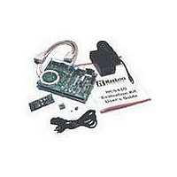
Kit Contents
Main Board, 2 Transmitters, Cables And Power Supply
Tool / Board Applications
General Purpose MCU, MPU, DSP, DSC
For Use With
KeeLoq
Lead Free Status / RoHS Status
Request inventory verification / Request inventory verification
For Use With/related Products
Keeloq Encoders & Decoders
Lead Free Status / RoHS Status
Lead free / RoHS Compliant, Request inventory verification / Request inventory verification


K
4.1
All Encoder models share a common code word format
composed of:
• 32-bit Hopping Code portion containing the
• 28-bit Serial Number that is the unique transmitter
• 4-bit Function Code indicating what button(s)
• 1 Low Voltage indication bit communicating to the
• 1 to 5, additional status bits depending on the
The Evaluation Kit II firmware attempts to receive only
the first 66 bits of any radio transmission. The GUI soft-
ware separates this data into the appropriate dialog
box fields after a successful reception.
The example in Figure 4-1 shows that:
• The Hopping Code received is A36FC5DD
• The transmitter Serial Number is 1234567
• The Function Code transmitted is 4 (S1 activated
• Status bits are
DS41155A-page 14
encrypted sychronization information
identifier
activated the transmitter. The Function Code is
sometimes combined with the serial number
creating a single 32-bit Extended Serial Number
decoder the transmitter battery status
encoder model.
on the transmitter)
the encoder used was an HCS300 they can be
interpreted as:
- Low Voltage =
- Repeat =
EE
L
OQ
Receiving K
®
1
EVALUATION KIT II USER’S GUIDE
0
0
and
1
EE
respectively. Assuming
L
OQ
Transmissions
16
16
4.2
PROBLEM:
The GUI software is unable to initialize the Main Board
and a Serial Communication Error message is dis-
played.
SOLUTIONS:
1.
2.
3.
4.
PROBLEM:
No transmissions are received:
SOLUTIONS:
1.
2.
3.
4.
Check that the RS-232 cable between the PC
and main board is in place.
Check that the Main Board is powered
appropriately.
Check that the correct serial port has been
selected.
Reset the main board.
Check that the connection between the decoder
and main board is correct.
Check that the RS-232 cable between the main
board and PC is in place.
Check that the JP1 jumper on the main board is
in place.
Check that the link JP1 on the Demo Transmitter
board is in place.
Troubleshooting
2001 Microchip Technology Inc.
Related parts for DM303006
Image
Part Number
Description
Manufacturer
Datasheet
Request
R

Part Number:
Description:
Manufacturer:
Microchip Technology Inc.
Datasheet:
Part Number:
Description:
Manufacturer:
Microchip Technology Inc.
Datasheet:
Part Number:
Description:
Manufacturer:
Microchip Technology Inc.
Datasheet:
Part Number:
Description:
Manufacturer:
Microchip Technology Inc.
Datasheet:
Part Number:
Description:
Manufacturer:
Microchip Technology Inc.
Datasheet:
Part Number:
Description:
Manufacturer:
Microchip Technology Inc.
Datasheet:
Part Number:
Description:
Manufacturer:
Microchip Technology Inc.
Datasheet:
Part Number:
Description:
Manufacturer:
Microchip Technology Inc.
Datasheet: