ADNK-3043-TI27 Avago Technologies US Inc., ADNK-3043-TI27 Datasheet
ADNK-3043-TI27
Specifications of ADNK-3043-TI27


Related parts for ADNK-3043-TI27


ADNK-3043-TI27 Summary of contents
Page 1
... ADNK-3043-TI27 Wireless USB Optical Mouse Designer’s Kit Design Guide Introduction This design guide describes the design of a low power consumption optical mouse using the Texas Instrument MSP430F1222 microcontroller, the Avago ADNS-3040 optical sensor and a 27 MHz FSK transmitter implemented with discrete components. The receiver is implemented with a TI TRF9700 receiver and Cypress CY7C63743 USB controller ...
Page 2
... Z Optics Signals Left Button Wheel Button Right Button Figure 1. ADNK-3034-TI27 Reference Design Mouse functional Block Diagram Theory of Operation Navigation Technology The heart of the ADNS-3040 navigation sensor is a CMOS image array. An LED and an optical system illuminate the surface that the ADNS-3040 is navigating on. The texture of the surface casts bright and dark spots forming distinct images as the sensor is moved across the surface ...
Page 3
Z Wheel The motion of Z-wheel is detected using the quadrature signal generated by optical sensors. Two phototransistors are connected in a source-follower configuration forming Channel A and Channel infrared LED shines, causing the phototransistors to turn ...
Page 4
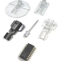
... MHz FSK transmitter circuit is based on a previously published reference design. Some details on ADNK-3043-TI27 The ADNK-3043-TI27 reference design kit allows users to evaluate the performance of the Optical Tracking Engine (sensor, lens, LED assembly clip, LED) over a 27 MHz RF connection. This kit also enables users to understand the recommended mechanical assembly ...
Page 5
... To Disassemble the ADNK-3043 TI27 Unit The ADNK-3034 TI27 comprises of the plastic mouse casing, a main printed circuit board (PCB), lens, buttons, and a 27 MHz RF daughter card, and a 27 MHz USB receiver dongle. (See Figure 4.) Removing the screws located at the base of the unit separate the top and the bottom of the mouse casing ...
Page 6
... See Appendix C for details. Reference Design Documentation – Gerber File The Gerber File presents detailed schematics used in ADNK-3043-TI27 in PCB layout form. The file for this reference design can be found in the Hardware Support files folder in the CD-Rom. Overall circuit A schematic of the overall circuit is shown in Appendix A of this document ...
Page 7
Firmware Implementation The firmware for this reference design is written in the C language. The following files are required to compile the mouse firmware. File MSP430_AVAGO_ADNS-3040.c CRC-8.c wm430_buttons.c wm430_system.c wm430_transmitter.c wm430_wheel.c The user should insert the receiver dongle into an ...
Page 8
Appendix A: Schematic Diagram of the Main Board 8 ...
Page 9
Figure A1. Schematic diagram of the RF Transmitter Board 9 ...
Page 10
Appendix B: Bill of Materials for Components Shown on schematic (Main Board and RF Board) Part Type Qty Optical Sensor Device 1 Optical Sensor LED 1 Optical Sensor Lens 1 Optical Sensor Clip 1 Microcontroller 1 DC/DC Converter 1 Z ...
Page 11
Description Qty Resistor (0603) 2 Resistor (0603) 1 Resistor (0603) 1 Resistor (0603) 1 Resistor (0603) 1 Resistor (0603) 4 Resistor (0603) 2 Resistor (0603) 1 Ceremic Capacitor (0603) 2 Ceremic Capacitor (0603) 2 Ceremic Capacitor (0603) 2 Ceremic Capacitor ...
Page 12
Appendix C: Base Plate Feature Figure C1: Illustration of base plate mounting features. 12 ADNS ADNS-3120-001 LENS RECESS DIMENSIONS: 31.5 x 17.0 mm KEY PYRAMID FEATURE: 2.50mm HEIGHT MAX. ...
Page 13
Appendix D: Sectional view of PCB assembly PCB Lens/Light Pipe Base Plate Surface Figure D1: Sectional view of PCB assembly highlighting all optical mouse components (optical mouse sensor, clip, lens, LED, PCB, and base plate). Appendix E: Receiver dongle Implementation ...
Page 14
... Trim Lens Plate ADNS-2220-001 LED Assembly Clip HLMP-ED80-PS000 ADNK-3043-TI27 CD Includes Documentation and Support Files for ADNK-3043-TI27 Documentation a. ADNS-3040 Ultra Low Power Optical Mouse Data Sheet b. ADNS-3120-001 Solid State Optical Mouse Lens Data Sheet c. ADNS-2220-001 LED Assembly Clip Data Sheet d. HLMP-ED80-XX000 LED Data Sheet e ...