ETRX2USB Telegesis Ltd, ETRX2USB Datasheet - Page 5
ETRX2USB
Manufacturer Part Number
ETRX2USB
Description
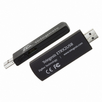
MODULE ZIGBEE USB STICK
Manufacturer
Telegesis Ltd
Specifications of ETRX2USB
Function
Transceiver, ZigBee
Modulation Or Protocol
802.15.4 Zigbee
Frequency
2.4GHz
Applications
ISM
Interface
USB
Sensitivity
-98dBm
Power - Output
3dBm
Data Rate - Maximum
250kbps
Voltage - Supply
4.75 V ~ 5.25 V
Package / Case
Module
Module Applications
Commissioning Tool When Setting Up Networks
Compliance Standard
IEEE 802.15.4
Supported Devices
ETRX2
Module Interface
RS232, USB
Supply Voltage Range
4.75V To 5.25V
Lead Free Status / RoHS Status
Lead free / RoHS Compliant
Features
-
Lead Free Status / RoHS Status
Lead free / RoHS Compliant, Lead free / RoHS Compliant
Other names
920-1002


5 ETRX2 I/O Connectivity
The I/Os of the built in ETRX2 are connected as follows:
Important Note: The lines for hardware handshaking are connected, so even when not using
hardware handshaking I/O2 should never be defined as an output as this would drive against the
incoming CTS signal via a 1kΩ resistor and increase the current consumption.
Note that if you use the command “AT&F” on the USB stick, I/O1 will revert to being an input and
the LED will not light up. To restore its function as a pilot light, use the command “ATS0E=00FA”
(with R2xx firmware) or “ATS17=00FA” (with R3xx) followed by a reset.
6 Firmware upgrades
The firmware which is loaded onto the embedded ETRX2 Module can be upgraded over the air or
via the virtual COM port as described in the Development Kit manual.
Alternatively, access to the SIF programming interface is possible by opening the cover on the side
of the ETRX2USB ZigBee USB stick.
©2009 Telegesis (UK) Ltd
•
•
•
I/O1 is connected to the LED (drive I/O1 low to sink LED).
I/O2 is the CTS input for the ETRX2. Make sure I/O2 is never defined as an output.
I/O4 is the RTS input for the ETRX2.
- 5 -
ETRX2USB Product Manual (Rev 1.05)
ETRX2USB
Related parts for ETRX2USB
Image
Part Number
Description
Manufacturer
Datasheet
Request
R

Part Number:
Description:
MODULE ZIGBEE EM250 CHIP ANT
Manufacturer:
Telegesis Ltd
Datasheet:

Part Number:
Description:
MODULE ZIGBEE W/PWR AMP
Manufacturer:
Telegesis Ltd
Datasheet:


Part Number:
Description:
KIT DEVELOPMENT FOR ETRX357
Manufacturer:
Telegesis Ltd
Datasheet:

Part Number:
Description:
MODULE ZIGBEE PWR AMP USB STICK
Manufacturer:
Telegesis Ltd
Datasheet:

Part Number:
Description:
ZIGBEE ETHERNET ACCESS POINT
Manufacturer:
Telegesis Ltd
Datasheet:

Part Number:
Description:
ZIGBEE ETHERNET ACCESS POINT
Manufacturer:
Telegesis Ltd
Datasheet:

Part Number:
Description:
MODULE ZIGBEE EM357 W/CHIP ANT
Manufacturer:
Telegesis Ltd
Datasheet:
Part Number:
Description:
MODULE ZIGBEE W/PA LNA CHIP ANT
Manufacturer:
Telegesis Ltd
Datasheet:
Part Number:
Description:
MODULE ZIGBEE W/PA LNA U.FL
Manufacturer:
Telegesis Ltd
Datasheet:
Part Number:
Description:
MODULE, ZIGBEE, ETRX351, CHIP ANT
Manufacturer:
Telegesis Ltd
Datasheet:
Part Number:
Description:
MODULE, ZIGBEE, ETRX3, HIROSE
Manufacturer:
Telegesis Ltd
Datasheet:
Part Number:
Description:
MODULE, ZIGBEE, ETRX3, PA+LNA, CHIP
Manufacturer:
Telegesis Ltd
Datasheet:
Part Number:
Description:
MODULE, ZIGBEE, ETRX3, PA+LNA, HIROS
Manufacturer:
Telegesis Ltd
Datasheet: