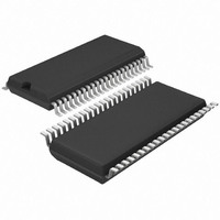
T4260-ILSH Atmel, T4260-ILSH Datasheet - Page 28

T4260-ILSH
Manufacturer Part Number
T4260-ILSH
Description
IC AM/FM FRONT END W/PLL 44SSOP
Manufacturer
Atmel
Datasheet
1.T4260-ILQH.pdf
(34 pages)
Specifications of T4260-ILSH
Frequency
AM, FM
Modulation Or Protocol
AM, FM
Applications
AM/FM Radio Receiver
Current - Receiving
85mA
Data Interface
PCB, Surface Mount
Antenna Connector
PCB, Surface Mount
Voltage - Supply
8 V ~ 10 V
Operating Temperature
-40°C ~ 85°C
Package / Case
44-SSOP
Lead Free Status / RoHS Status
Lead free / RoHS Compliant
Features
-
Sensitivity
-
Memory Size
-
Data Rate - Maximum
-
11.5
11.6
28
Charge Pump Current Settings
AM Prescaler (Divider) Settings
T4260
If the fractional mode is switched off (bit 144 = 1) during direct shift mode (bit 32 = 0), the modulo
value of the N-divider will be ignored (the new N-divider is then 2278 instead of 2278.25). This
means that the PLL locks on the next lower multiple frequency of 4
f
fractional mode).
Also the PLL has additionally a special fractional logic which allows a good spurious suppression
in the fractional and direct shift mode. Activating the wire switch (bit 60 = 1) and the correction
charge pump (bit 60 = 1) the spurious suppression is active.
Bit 62 (0 = 1 mA; 1 = 2 mA) allows to adjust the high current, which is active during a frequency
change (if the delay time of the active HCDEL register is not switched off). A high charge pump
current allows faster frequency changes. After a frequency change, the current reduction is
reduced (in locked mode) to the low current which is set by bit 63 (0 = 50 µA; 1 = 100 µA). A
lower charge pump current guarantees a higher S/N ratio.
The high current charge pump can be switched off by the active HCDEL register bits. In this
case, when HCDEL 1 is active and the bits 20 and 21 are 0 (HCDEL 1 delay time = off) or
HCDEL 2 is active and the bits 22 and 23 are 0 (HCDEL 2 delay time = off), only the low current
charge pump (current) is active in locked and in the frequency change mode.
The AM mixer is used for up-conversion of the AM reception frequency to the IF frequency.
Therefore, an AM prescaler is implemented to generate the necessary LO from the VCO fre-
quency. For the reception of the AM band, different prescaler (divider) settings are possible.
Table 11-1 on page 29
f
f
f
f
The following formula can also be useful by AM frequencies higher than 20 MHz:
f
PDF
VCO
IF
rec
VCO
VCO
= 10.7 MHz
= f
= 12.5 kHz). The new VCO frequency (f
= 98.2 MHz to 124 MHz
= AM prescaler
= AM prescaler
VCO
– f
IF
x
x
(f
(f
lists the AM prescaler (divider) settings and the reception frequencies.
rec
rec
+ f
– f
IF
IF
)
)
VCO
) is then 113.9 MHz (instead of 113.9125 MHz in
f
PDF
4528N–AUDR–11/09
(in our case


