ATMEGA64RZAV-10PU Atmel, ATMEGA64RZAV-10PU Datasheet - Page 299
ATMEGA64RZAV-10PU
Manufacturer Part Number
ATMEGA64RZAV-10PU
Description
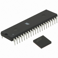
MCU ATMEGA644/AT86RF230 40-DIP
Manufacturer
Atmel
Series
ATMEGAr
Datasheets
1.ATMEGA644-20MU.pdf
(23 pages)
2.ATMEGA644-20MU.pdf
(376 pages)
3.AT86RF230-ZU.pdf
(98 pages)
Specifications of ATMEGA64RZAV-10PU
Frequency
2.4GHz
Modulation Or Protocol
802.15.4 Zigbee
Power - Output
3dBm
Sensitivity
-101dBm
Voltage - Supply
1.8 V ~ 3.6 V
Data Interface
PCB, Surface Mount
Memory Size
64kB Flash, 2kB EEPROM, 4kB RAM
Antenna Connector
PCB, Surface Mount
Package / Case
40-DIP (0.600", 15.24mm)
Wireless Frequency
2.4 GHz
Interface Type
JTAG, SPI
Output Power
3 dBm
For Use With
ATSTK600-TQFP32 - STK600 SOCKET/ADAPTER 32-TQFPATAVRISP2 - PROGRAMMER AVR IN SYSTEMATSTK500 - PROGRAMMER AVR STARTER KIT
Lead Free Status / RoHS Status
Lead free / RoHS Compliant
Operating Temperature
-
Applications
-
Data Rate - Maximum
-
Current - Transmitting
-
Current - Receiving
-
Lead Free Status / Rohs Status
Lead free / RoHS Compliant
For Use With/related Products
ATmega64


25.8
25.8.1
2593N–AVR–07/10
Serial Downloading
Serial Programming Pin Mapping
Table 25-14. Parallel Programming Characteristics, V
Notes:
Both the Flash and EEPROM memory arrays can be programmed using a serial programming
bus while RESET is pulled to GND. The serial programming interface consists of pins SCK,
MOSI (input) and MISO (output). After RESET is set low, the Programming Enable instruction
needs to be executed first before program/erase operations can be executed. NOTE, in
25-15 on page
SPI pins dedicated for the internal Serial Peripheral Interface - SPI.
Table 25-15. Pin Mapping Serial Programming
Figure 25-10. Serial Programming and Verify
Notes:
Symbol
t
t
t
t
XLOL
BVDV
OLDV
OHDZ
Symbol
MOSI
MISO
1. t
2. t
1. If the device is clocked by the internal Oscillator, it is no need to connect a clock source to the
2. V
SCK
commands.
XTAL1 pin.
WLRH
WLRH_CE
CC
Parameter
XTAL1 Low to OE Low
BS1 Valid to DATA valid
OE Low to DATA Valid
OE High to DATA Tri-stated
- 0.3V < AVCC < V
299, the pin mapping for serial programming is listed. Not all packages use the
is valid for the Write Flash, Write EEPROM, Write Fuse bits and Write Lock bits
is valid for the Chip Erase command.
(PDIP-40)
Pins
PB5
PB6
PB7
MOSI
MISO
SCK
CC
+ 0.3V, however, AVCC should always be within 1.8V - 5.5V
XTAL1
RESET
GND
(TQFP-44)
(1)
Pins
PB5
PB6
PB7
AVCC
VCC
CC
= 5V ±10% (Continued)
+1.8V - 5.5V
+1.8V - 5.5V
I/O
O
Min
I
I
(2)
0
0
Typ
ATmega644
Serial Data out
Serial Data in
Description
Serial Clock
Max
250
250
250
Units
ns
Table
299
Related parts for ATMEGA64RZAV-10PU
Image
Part Number
Description
Manufacturer
Datasheet
Request
R

Part Number:
Description:
DEV KIT FOR AVR/AVR32
Manufacturer:
Atmel
Datasheet:

Part Number:
Description:
INTERVAL AND WIPE/WASH WIPER CONTROL IC WITH DELAY
Manufacturer:
ATMEL Corporation
Datasheet:
Part Number:
Description:
Low-Voltage Voice-Switched IC for Hands-Free Operation
Manufacturer:
ATMEL Corporation
Datasheet:
Part Number:
Description:
MONOLITHIC INTEGRATED FEATUREPHONE CIRCUIT
Manufacturer:
ATMEL Corporation
Datasheet:
Part Number:
Description:
AM-FM Receiver IC U4255BM-M
Manufacturer:
ATMEL Corporation
Datasheet:
Part Number:
Description:
Monolithic Integrated Feature Phone Circuit
Manufacturer:
ATMEL Corporation
Datasheet:
Part Number:
Description:
Multistandard Video-IF and Quasi Parallel Sound Processing
Manufacturer:
ATMEL Corporation
Datasheet:
Part Number:
Description:
High-performance EE PLD
Manufacturer:
ATMEL Corporation
Datasheet:
Part Number:
Description:
8-bit Flash Microcontroller
Manufacturer:
ATMEL Corporation
Datasheet:
Part Number:
Description:
2-Wire Serial EEPROM
Manufacturer:
ATMEL Corporation
Datasheet: