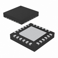
SX1231IMLTRT Semtech, SX1231IMLTRT Datasheet - Page 31

SX1231IMLTRT
Manufacturer Part Number
SX1231IMLTRT
Description
IC 433/868/915MHZ TXRX 24-QFN
Manufacturer
Semtech
Specifications of SX1231IMLTRT
Frequency
433MHz, 868MHz, 915MHz
Data Rate - Maximum
300kbps
Modulation Or Protocol
FSK, GFSK, GMSK, MSK, OOK
Applications
AMR, Home Automation, Security
Power - Output
13dBm
Sensitivity
-118dBm
Voltage - Supply
1.8 V ~ 3.6 V
Current - Receiving
16mA
Current - Transmitting
95mA
Data Interface
PCB, Surface Mount
Antenna Connector
PCB, Surface Mount
Operating Temperature
-40°C ~ 85°C
Package / Case
24-QFN
Transmitting Current
95mA
Data Rate
300Kbps
Rf Ic Case Style
QFN
No. Of Pins
24
Supply Voltage Range
1.8V To 3.6V
Operating Temperature Range
-40°C To +85°C
Receiving Current
16mA
Lead Free Status / RoHS Status
Lead free / RoHS Compliant
Memory Size
-
Lead Free Status / Rohs Status
Compliant
Other names
SX1231IMLTR
Available stocks
Company
Part Number
Manufacturer
Quantity
Price
Company:
Part Number:
SX1231IMLTRT
Manufacturer:
ATMEL
Quantity:
1 200
Part Number:
SX1231IMLTRT
Manufacturer:
SEMTECHCORPORATION
Quantity:
20 000
When the AFC is automatically triggered (AfcAutoOn = 1), the user has the option to:
The SX1231 offers an alternate receiver bandwidth setting during the AFC phase, to accommodate large LO drifts. If the
user considers that the received signal may be out of the receiver bandwidth, a higher channel filter bandwidth can be
programmed in RegAfcBw, at the expense of the receiver noise floor, which will impact upon sensitivity.
3.5.15. Optimized Setup for Low Modulation Index Systems
The user should ensure that the programmed offset exceeds the DC canceller’s cutoff frequency, set through DccFreqAfc
in RegAfcBw.
As shown on Figure 13, a standard AFC sequence uses the result of the FEI to correct the LO frequency and align both
local oscillators. When the optimized AFC is enabled (AfcLowBetaOn=1), the receiver’s LO is corrected by “FeiValue +
LowBetaAfcOffset”.
When the optimized AFC routine is enabled, the receiver startup time can be computed as follows (refer to section 4.2.3):
Rev 3 - April 2010
ADVANCED COMMUNICATIONS & SENSING
Clear the former AFC correction value, if AfcAutoClearOn = 1
Start the AFC evaluation from the previously corrected frequency. This may be useful in systems in which the LO keeps
on drifting in the “same direction”. Ageing compensation is a good example.
For wide band systems, where AFC is usually not required (XTAL inaccuracies do not typically impact the sensitivity), it
is recommended to offset the LO frequency of the receiver to avoid desensitization. This can be simply done by
modifying Frf in RegFrfLsb. A good rule of thumb is to offset the receiver’s LO by 10% of the expected transmitter
frequency deviation.
For narrow band systems, it is recommended to perform AFC. The SX1231 has a dedicated AFC, enabled when
AfcLowBetaOn in RegAfcCtrl is set to 1. A frequency offset, programmable through LowBetaAfcOffset in RegTestAfc, is
added and is calculated as follows:
TS_RE_AGC&AFC (optimized AFC) = Tana + 4.Tcf + 4.Tdcc + 3.Trssi + 2.Tafc + 2.Tpllafc
RX
RX
Before AFC
FeiValue
FeiValue
Figure 13. Optimized AFC (AfcLowBetaOn=1)
TX
TX
Offset = LowBetaAfcOffset x 488 Hz
f
f
Standard AFC
AfcLowBetaOn = 0
Optimized AFC
AfcLowBetaOn = 1
Page 31
After AFC
AfcValue
AfcValue
RX
TX
&
TX
RX
LowBetaAfcOffset
f
f
DATASHEET
www.semtech.com
SX1231


