MC13202FC Freescale Semiconductor, MC13202FC Datasheet - Page 12
MC13202FC
Manufacturer Part Number
MC13202FC
Description
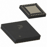
IC TXRX RF 2.4GHZ 32-QFN
Manufacturer
Freescale Semiconductor
Datasheet
1.MC13202FCR2.pdf
(30 pages)
Specifications of MC13202FC
Frequency
2.4GHz
Data Rate - Maximum
250kbps
Modulation Or Protocol
802.15.4
Applications
AMR, HID, HVAC, ISM
Power - Output
-27dBm ~ 3dBm
Sensitivity
-92dBm
Voltage - Supply
2 V ~ 3.4 V
Current - Receiving
37mA
Current - Transmitting
30mA
Data Interface
PCB, Surface Mount
Antenna Connector
PCB, Surface Mount
Operating Temperature
-40°C ~ 85°C
Package / Case
32-QFN
Operating Supply Voltage
2.7 V
Mounting Style
SMD/SMT
Minimum Operating Temperature
- 40 C
Operating Temperature (min)
-40C
Operating Temperature (max)
85C
Operating Temperature Classification
Industrial
Lead Free Status / RoHS Status
Lead free / RoHS Compliant
Memory Size
-
Lead Free Status / Rohs Status
Lead free / RoHS Compliant


6
The following sections provide a detailed description of the MC13202 functionality including the
operating modes and Serial Peripheral Interface (SPI).
6.1
The MC13202 has a number of operational modes that allow for low-current operation. Transition from
the Off to Idle mode occurs when RST is negated. Once in Idle, the SPI is active and is used to control the
IC. Transition to Hibernate and Doze modes is enabled via the SPI. These modes are summarized, along
with the transition times, in
Characteristics.
6.2
The host microcontroller directs the MC13202, checks its status, and reads/writes data to the device
through the 4-wire SPI port. The transceiver operates as a SPI slave device only. A transaction between
the host and the MC13202 occurs as multiple 8-bit bursts on the SPI. The SPI signals are:
12
Hibernate Crystal Reference Oscillator Off. (SPI not functional.) IC Responds to ATTN. Data is
Transmit
Receive
Mode
Doze
1. Chip Enable (CE) - A transaction on the SPI port is framed by the active low CE input signal. A
2. SPI Clock (SPICLK) - The host drives the SPICLK input to the MC13202. Data is clocked into the
3. Master Out/Slave In (MOSI) - Incoming data from the host is presented on the MOSI input.
4. Master In/Slave Out (MISO) - The MC13202 presents data to the master on the MISO output.
Idle
Off
Functional Description
transaction is a minimum of 3 SPI bursts and can extend to a greater number of bursts.
master or slave on the leading (rising) edge of the return-to-zero SPICLK and data out changes
state on the trailing (falling) edge of SPICLK.
MC13202 Operational Modes
Serial Peripheral Interface (SPI)
All IC functions Off, Leakage only. RST asserted. Digital outputs are tri-stated
including IRQ
retained.
Crystal Reference Oscillator On but CLKO output available only if Register 7, Bit 9 =
1 for frequencies of 1 MHz or less. (SPI not functional.) Responds to ATTN and can
be programmed to enter Idle Mode through an internal timer comparator.
Crystal Reference Oscillator On with CLKO output available. SPI active.
Crystal Reference Oscillator On. Receiver On.
Crystal Reference Oscillator On. Transmitter On.
For Freescale microcontrollers, the SPI clock format is the clock phase
control bit CPHA = 0 and the clock polarity control bit CPOL = 0.
Table 8. MC13202 Mode Definitions and Transition Times
Table
8. Current drain in the various modes is listed in
MC13202 Technical Data, Rev. 1.5
Definition
NOTE
Table
10 - 25 ms to Idle
7 - 20 ms to Idle
(300 + 1/CLKO) µs to Idle
144 µs from Idle
144 µs from Idle
Freescale Semiconductor
Transition Time
To or From Idle
3, DC Electrical
Related parts for MC13202FC
Image
Part Number
Description
Manufacturer
Datasheet
Request
R

Part Number:
Description:
Manufacturer:
Freescale Semiconductor, Inc
Datasheet:
Part Number:
Description:
Manufacturer:
Freescale Semiconductor, Inc
Datasheet:
Part Number:
Description:
Manufacturer:
Freescale Semiconductor, Inc
Datasheet:
Part Number:
Description:
Manufacturer:
Freescale Semiconductor, Inc
Datasheet:
Part Number:
Description:
Manufacturer:
Freescale Semiconductor, Inc
Datasheet:
Part Number:
Description:
Manufacturer:
Freescale Semiconductor, Inc
Datasheet:
Part Number:
Description:
Manufacturer:
Freescale Semiconductor, Inc
Datasheet:
Part Number:
Description:
Manufacturer:
Freescale Semiconductor, Inc
Datasheet:
Part Number:
Description:
Manufacturer:
Freescale Semiconductor, Inc
Datasheet:
Part Number:
Description:
Manufacturer:
Freescale Semiconductor, Inc
Datasheet:
Part Number:
Description:
Manufacturer:
Freescale Semiconductor, Inc
Datasheet:
Part Number:
Description:
Manufacturer:
Freescale Semiconductor, Inc
Datasheet:
Part Number:
Description:
Manufacturer:
Freescale Semiconductor, Inc
Datasheet:
Part Number:
Description:
Manufacturer:
Freescale Semiconductor, Inc
Datasheet:
Part Number:
Description:
Manufacturer:
Freescale Semiconductor, Inc
Datasheet: