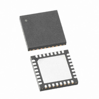
SX1212IWLTRT Semtech, SX1212IWLTRT Datasheet - Page 44

SX1212IWLTRT
Manufacturer Part Number
SX1212IWLTRT
Description
IC TXRX 300MHZ-510MHZ 32-TQFN
Manufacturer
Semtech
Datasheet
1.SX1212IWLTRT.pdf
(77 pages)
Specifications of SX1212IWLTRT
Frequency
300MHz ~ 510MHz
Data Rate - Maximum
150kbps
Modulation Or Protocol
FSK, OOK
Applications
AMR, ISM, Home Automation, Process Control
Power - Output
12.5dBm
Sensitivity
-110dBm
Voltage - Supply
2.1 V ~ 3.6 V
Current - Receiving
3mA
Current - Transmitting
25mA
Data Interface
PCB, Surface Mount
Antenna Connector
PCB, Surface Mount
Operating Temperature
-40°C ~ 85°C
Package / Case
32-TQFN
Operating Temperature (min)
-40C
Operating Temperature (max)
85C
Operating Temperature Classification
Industrial
Modulation Type
FSK/OOK
Package Type
TQFN EP
Operating Supply Voltage (min)
2.1V
Operating Supply Voltage (typ)
2.5/3.3V
Operating Supply Voltage (max)
3.6V
Lead Free Status / RoHS Status
Lead free / RoHS Compliant
Memory Size
-
Lead Free Status / Rohs Status
Supplier Unconfirmed
Other names
SX1212IWLTR
Available stocks
Company
Part Number
Manufacturer
Quantity
Price
Part Number:
SX1212IWLTRT
Manufacturer:
SEMTECH/美国升特
Quantity:
20 000
As illustrated in Figure 38, for Buffered mode operation the NRZ data to (from) the (de)modulator is not directly
accessed by the uC but stored in the FIFO and accessed via the SPI Data interface. This frees the uC for other
tasks between processing data from the SX1212, furthermore it simplifies software development and reduces uC
performance requirements (speed, reactivity). Note that in this mode the packet handler stays inactive.
An important feature is also the ability to empty the FIFO in Stby mode, ensuring low power consumption and
adding greater software flexibility.
Note that Bit Synchronizer is automatically enabled in Buffered mode.
activated by the user if needed.
After entering Tx in Buffered mode, the chip expects the uC to write into the FIFO, via the SPI Data interface, all the
data bytes to be transmitted (preamble, Sync word, payload...).
Actual transmission of first byte will start either when the FIFO is not empty (i.e. first byte written by the uC) or when
the FIFO is full depending on bit IRQParam_Tx_start_irq_0.
In Buffered mode the packet length is not limited, i.e. as long as there are bytes inside the FIFO they are sent.
When the last byte is transferred to the SR, /Fifoempty IRQ source is asserted to warn the uC, at that time FIFO
can still be filled with additional bytes if needed.
When the last bit of the last byte has left the SR (i.e. 8 bit periods later), the Tx_done interrupt source is asserted
and the user can exit Tx mode after waiting at least 1 bit period from the last bit processed by modulator.
Rev 2 – June 18th, 2009
ADVANCED COMMUNICATIONS & SENSING
Data
5.4. Buffered Mode
Datapath
5.4.1. General Description
5.4.2. Tx Processing
Tx
Rx
RECOG.
SYNC
Figure 38: Buffered Mode Conceptual View
SX1212
CONTROL
Page 44 of 77
(+SR)
FIFO
The Sync word recognition must be
CONFIG
DATA
SPI
www.semtech.com
NSS_CONFIG
MISO
SCK
MOSI
NSS_DATA
IRQ_1
SX1212
IRQ_0


