RN-24S Roving Networks Inc, RN-24S Datasheet - Page 3
RN-24S
Manufacturer Part Number
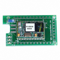
RN-24S
Description
SUPERMODULE BLUETOOTH CHIP ANT
Manufacturer
Roving Networks Inc
Specifications of RN-24S
Frequency
2.4GHz
Data Rate - Maximum
721kbps
Modulation Or Protocol
Bluetooth v2.0+EDR, Class 1 & 2
Applications
Bluetooth v2.0
Power - Output
4dBm
Sensitivity
-80dBm
Voltage - Supply
4 V ~ 24 V
Current - Receiving
40mA
Current - Transmitting
40mA
Data Interface
PCB, Surface Mount
Antenna Connector
On-Board, Chip
Package / Case
Module
Wireless Frequency
2.402 GHz to 2.48 GHz
Interface Type
UART
Data Rate
240 Kbps to 300 Kbps
Modulation
FHSS, GFSK
Operating Voltage
3.3 V
Antenna
Chip Antenna
Board Size
20.32 mm x 50.8 mm x 4.08 mm
Lead Free Status / RoHS Status
Lead free / RoHS Compliant
Operating Temperature
-
Memory Size
-
Lead Free Status / Rohs Status
Lead free / RoHS Compliant
Other names
740-1008


The Power-up settings for the GPIO can also be viewed using the “E” (extended settings)
command.
WARNING:
GPIO-4 is used by the system to reset stored parameters to factory defaults. If GPIO4 is
pulled high on power-up, and then toggled 3 times, all user settings will return to default
values. Therefore this pin should not be used as an output, and should not be driven high
at power-up time (first 1 second of operation).
NOTE:
the direction command, (to save power, for example) and used as inputs. If set to
outputs the software will override any user values.
SETTING GPIO 8-9-10-11:
S*,<hexword> = MASK[11..8] VALUE[11..8]
For the upper 4 GPIO, a single word controls the mask and values, and only the lower 4
bits of each byte are used. The first time this command is used, all 4 GPIO are driven as
outputs and remain so until a power cycle. There is no powerup command for these bits,
only the interactive one.
Examples:
(and is driven in command mode and manual data mode),
GPIO10 and 11 are available on the 8 pin thru hole header on the
board edge. GPIO11 is the SQUARE pin, and GPIO 10 is the 3rd
pin down from GPIO11.
Roving Networks RN-24 V 4.22 5/31/2007
S*,0101
S*,0100
S*,0202
GPIO8 pulls the YELLOW LED on when low, GPIO9 pulls the RED LED on when low
GPIO2 and 5 are driven by the embedded software as outputs, they can be disabled using
GPIO-8 driven LOW.
GPIO-8 driven HIGH.
GPIO-9 driven HIGH.
page 6
Making a Connection
bytes of the Bluetooth address. To connect to RN-24, browse for services, you should
see: “SPP on Blueport-zpdq”. Default baudrate is 115200, no parity, 8 bits, 1 stop.
RN-24 uses Serial Port Profile and can be connected to as a Virtual COM port on PCs,
Palms, PocketPCs, or other clients.
NOTE: Only one client can connect to RN-24 at a time, and there is a limit of 7 total
devices in a Bluetooth Piconet network.
Changing Configuration
FROM LOCAL SERIAL PORT- Connect a null-modem cable (pins 2,3 swapped) from a
PC or a straight cable from an ASCII terminal to the RN-24. Communication settings of
your program should match the stored settings, for example: the default is 115,200Kbps,
8 bits, No Parity, 1 stop bit. Once you change these parameters, they will be stored
permanently.
Run your favorite terminal emulator, hyperterminal or other program. (a free emulator for
the PC is available at www.rovingnetworks.com /support/teraterm.zip) ) Type $$$ on your
screen (3 dollar signs). You should see CMD returned to you. This will verify that your
cable and settings are correct. Valid commands will return an AOK. Errors in format will
return ERR, and unrecognized commands will return a ?.
commands, and “d”<cr> to see a summary of current settings.
REMOTE VIA BLUETOOTH- Make a connection via bluetooth, then use your favorite
terminal emulator, and follow the directions above for local configuration. To return to data
mode, type a final “---“ ( 3 minus signs) <cr>, or reset the device and connect again.
NOTE: remote configuration can only occur if the bootup configuration timer (default 60
seconds) has not expired. This timer is set to 0 ( remote config disabled) for master
mode, and auto-connect slave mode, so that data can immediately flow between the 2
devices in cable replacement fashion.
Roving Networks RN-24 V 4.22 5/31/2007
RN-24 shows up under Service discovery as “FireFly-zpdq” where the zpdq is the last 2
Type “h”<cr> to see a list of
page 3
Related parts for RN-24S
Image
Part Number
Description
Manufacturer
Datasheet
Request
R

Part Number:
Description:
ADAPTER BLUETOOTH FRFLY SRL FEML
Manufacturer:
Roving Networks Inc
Datasheet:

Part Number:
Description:
ADAPTER BLUETOOTH FRFLY SRL MALE
Manufacturer:
Roving Networks Inc
Datasheet:

Part Number:
Description:
ADAPTER BLUETOOTH FIREFLY RS422
Manufacturer:
Roving Networks Inc
Datasheet:

Part Number:
Description:
SUPERMODULE BLUETOOTH SMA JACK
Manufacturer:
Roving Networks Inc
Datasheet:

Part Number:
Description:
MODULE BLUETOOTH V2.1+EDR
Manufacturer:
Roving Networks Inc
Datasheet:

Part Number:
Description:
MODULE BLUETOOTH V2.1+EDR
Manufacturer:
Roving Networks Inc
Datasheet:

Part Number:
Description:
ANTENNA 2.4GHZ 4" SMA MALE
Manufacturer:
Roving Networks Inc
Datasheet:

Part Number:
Description:
ADAPTER BLUETOOTH 2.0 USB
Manufacturer:
Roving Networks Inc
Datasheet:

Part Number:
Description:
ADAPTER BLUETOOTH USB DRIVERLESS
Manufacturer:
Roving Networks Inc
Datasheet:

Part Number:
Description:
MODULE BLUETOOTH V2.0+EDR
Manufacturer:
Roving Networks Inc
Datasheet:

Part Number:
Description:
MODULE BLUETOOTH W/ANT CLASS1
Manufacturer:
Roving Networks Inc
Datasheet:

Part Number:
Description:
MODULE BLUETOOTH 2.0/EDR CLASS1
Manufacturer:
Roving Networks Inc
Datasheet:

Part Number:
Description:
MODULE BLUETOOTH AUDIO V1.2
Manufacturer:
Roving Networks Inc
Datasheet:

Part Number:
Description:
MODULE SOCKET BLUETOOTH CLASS1
Manufacturer:
Roving Networks Inc
Datasheet:
Part Number:
Description:
MODULE BLUETOOTH V2.1+EDR
Manufacturer:
Roving Networks Inc
Datasheet: