RN-24S Roving Networks Inc, RN-24S Datasheet - Page 4
RN-24S
Manufacturer Part Number
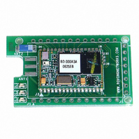
RN-24S
Description
SUPERMODULE BLUETOOTH CHIP ANT
Manufacturer
Roving Networks Inc
Specifications of RN-24S
Frequency
2.4GHz
Data Rate - Maximum
721kbps
Modulation Or Protocol
Bluetooth v2.0+EDR, Class 1 & 2
Applications
Bluetooth v2.0
Power - Output
4dBm
Sensitivity
-80dBm
Voltage - Supply
4 V ~ 24 V
Current - Receiving
40mA
Current - Transmitting
40mA
Data Interface
PCB, Surface Mount
Antenna Connector
On-Board, Chip
Package / Case
Module
Wireless Frequency
2.402 GHz to 2.48 GHz
Interface Type
UART
Data Rate
240 Kbps to 300 Kbps
Modulation
FHSS, GFSK
Operating Voltage
3.3 V
Antenna
Chip Antenna
Board Size
20.32 mm x 50.8 mm x 4.08 mm
Lead Free Status / RoHS Status
Lead free / RoHS Compliant
Operating Temperature
-
Memory Size
-
Lead Free Status / Rohs Status
Lead free / RoHS Compliant
Other names
740-1008


CMD
CMD
CMD
COMMAND SUMMARY
***SET COMMANDS ***stored in flash, and only take effect AFTER reboot
*** DISPLAY COMMANDS ***
*** OTHER COMMANDS
Example: SU,9600
Roving Networks RN-24 V 4.22 5/31/2007
G<X>
SA
SE
SF
SL
SM 0,1,2,3
SN
SO
SP
SR
ST
SU
SX
D
E
GB
&
C
H
R
U
V
0,1
0,1
E,O,N
string
string
string
string
word
string
0,1
<addr>
VALUE
VAL1
<rate> <E,O,N>
1
1
SP,secret
SN,myname sets Bluetooth name to “myname”
SA,1
SF,1
DESCRIPTION
Basic Settings
Extended Settings
A single setting matching the commands above
Bluetooth Address of this device
I/O Ports (shows the value of the switches)
Firmware Revision
TYPE
dec
dec
dec
char
dec
1-16 char Blueport-x Bluetooth Name
1-8
1-16 char 1234
seconds
2-4 char
dec
VAL2
12 chars NOT SET Remote Address (123456789ABCDEF)
restores all values to factory defaults
sets security pincode to “secret”
enables secure authentication
sets Uart Baudrate to 9600
DEFAULT DESCRIPTION
60
DESCRIPTION
0
0
N
0
NULL
115K
0
Connect to Remote Address
Help, Show list of commands
Reboot device immediate
Temporary UART Change, immediate, not stored
***
Send connect/disconnect status string
Security Pin Code
Baudrate:1200,2400,4800,9600,19.2,38.4,
57.6,115k,230k,460k)
Enable Authentication
Enable encryption
Reset to Factory Defaults
Parity, Even, Odd, or None
Config Timer(0=no config, 255=always on)
Bonding (locks to a single remote address)
Mode (0-slav,1=mstr, 2=trig,3=auto ,4=DTR)
page 4
CMD
NOTE:
www.rovingnetworks.com
*** COMMANDS to MANIPULATE GPIO ***
The GPIO command interface uses combination of 2bytes, a mask, and value, packed
into a hex word for each command. The first byte, the mask, determines which GPIO
are to be affected, and the second byte is the value to set.
<hexword> = MASK[7...0] VALUE[7..0]
There are 2 registers used to control the GPIO, the first is a direction register. This
controls whether the GPIO is an input or an output. The second register is the value to
apply to the GPIO if set to an output, or is the value of the built-in weak pull-up resistor if
the GPIO is set to an input. These settings are immediate, and do not survive a power
cycle.
Examples: S@,8080
Power-up values: These 2 registers will apply the direction and values upon each
subsequent power-up:
Examples: S%,0101
Multiple bits can be set, any bits with a mask of 0 are left unaffected for the command.
Some GPIO are checked at power-up time to perform certain functions, so care must be
taken when manipulating them. GPIO3, 6, are used to automatically set master mode,
and auto discovery. If it is desired to use these GPIO for other purposes at power-up, a
special command must be used to disable their being sensed at power-up time. This
command is “SQ,4<cr>” this will set a flag in a stored register that is read at power-up.
Roving Networks RN-24 V 4.22 5/31/2007
*
@ <hexword> Set direction bits for GPIO
&
% <hexword> Store powerup direction bits for GPIO
^
<hexword> Set values for GPIO
<hexword> Store powerup values for GPIO
<hexword> Set values for PIO8,9,10,11
VALUE
S&,8080
S&,8000
S^,0303
There are many other commands available,
15 --------- 8 7 -------- 0
DESCRIPTION
sets GPIO-0 to an output on power-up
drives GPIO-0 high, and pulls up GPIO-1.
sets GPIO-7 to an output
drives GPIO-7 high
drives GPIO-7 low
for an extensive software user manual.
page 5
visit
Related parts for RN-24S
Image
Part Number
Description
Manufacturer
Datasheet
Request
R

Part Number:
Description:
ADAPTER BLUETOOTH FRFLY SRL FEML
Manufacturer:
Roving Networks Inc
Datasheet:

Part Number:
Description:
ADAPTER BLUETOOTH FRFLY SRL MALE
Manufacturer:
Roving Networks Inc
Datasheet:

Part Number:
Description:
ADAPTER BLUETOOTH FIREFLY RS422
Manufacturer:
Roving Networks Inc
Datasheet:

Part Number:
Description:
SUPERMODULE BLUETOOTH SMA JACK
Manufacturer:
Roving Networks Inc
Datasheet:

Part Number:
Description:
MODULE BLUETOOTH V2.1+EDR
Manufacturer:
Roving Networks Inc
Datasheet:

Part Number:
Description:
MODULE BLUETOOTH V2.1+EDR
Manufacturer:
Roving Networks Inc
Datasheet:

Part Number:
Description:
ANTENNA 2.4GHZ 4" SMA MALE
Manufacturer:
Roving Networks Inc
Datasheet:

Part Number:
Description:
ADAPTER BLUETOOTH 2.0 USB
Manufacturer:
Roving Networks Inc
Datasheet:

Part Number:
Description:
ADAPTER BLUETOOTH USB DRIVERLESS
Manufacturer:
Roving Networks Inc
Datasheet:

Part Number:
Description:
MODULE BLUETOOTH V2.0+EDR
Manufacturer:
Roving Networks Inc
Datasheet:

Part Number:
Description:
MODULE BLUETOOTH W/ANT CLASS1
Manufacturer:
Roving Networks Inc
Datasheet:

Part Number:
Description:
MODULE BLUETOOTH 2.0/EDR CLASS1
Manufacturer:
Roving Networks Inc
Datasheet:

Part Number:
Description:
MODULE BLUETOOTH AUDIO V1.2
Manufacturer:
Roving Networks Inc
Datasheet:

Part Number:
Description:
MODULE SOCKET BLUETOOTH CLASS1
Manufacturer:
Roving Networks Inc
Datasheet:
Part Number:
Description:
MODULE BLUETOOTH V2.1+EDR
Manufacturer:
Roving Networks Inc
Datasheet: