ATA8404-6DQY Atmel, ATA8404-6DQY Datasheet
ATA8404-6DQY
Specifications of ATA8404-6DQY


Related parts for ATA8404-6DQY


ATA8404-6DQY Summary of contents
Page 1
... High Output Power (6 dBm) • Low Current Consumption at 8.1 mA (315 MHz) and 8.5 mA (433 MHz) • Divide by 24 (ATA8404) and 32 (ATA8405) Blocks for 13 MHz Crystal Frequencies and for Low XTO Start-up Times • ASK/FSK Modulation with Internal FSK Switch • ...
Page 2
... ASK modulation and enables the PLL and XTO if the ENABLE pin is open. Switches off the FSK switch (switch has high Z if signal at pin FSK is High) and 3 FSK enables the PLL and the XTO if the ENABLE pin is open ATA8404/ATA8405 [Preliminary CLK ASK 2 9 ...
Page 3
... If ENABLE is connected to GND and the ASK or FSK pin is High, the device 10 ENABLE stays in idle mode. In normal operation ENABLE is left open and ASK or FSK is used to enable the device. 9136C–INDCO–10/09 ATA8404/ATA8405 [Preliminary] Configuration (FSK < 0.25V) AND (ENABLE > 1.7V) XTO2 VS 1.5k XTO1 182 µ ...
Page 4
... CLK output activation. This means an additional wait time of necessary before the PA can be switched on and the data transmission can start. This results in a significantly lower time of about 0.85 ms between enabling the ATA8404/ATA8405 and the beginning of the data transmission which saves battery power. ...
Page 5
... Table 4-1. ASK Pin Low Low Low High High Low/High High 9136C–INDCO–10/09 ATA8404/ATA8405 [Preliminary] = 380 + j340 (ATA8404) at 315 MHz and Z ATA8404/ATA8405 Modes FSK Pin ENABLE Pin Low Low/open Low High High High/open Low High/open ...
Page 6
... Transmission with ENABLE = open 4.1.1 ASK Mode The ATA8404/ATA8405 is activated by ENABLE = open, FSK = High, ASK = Low. The micro- controller is then switched to external clocking. After typically 0.6 ms, the CLK driver is activated automatically (i.e., the microcontroller waits until the XTO and CLK are ready). After another time period of 250 µ ...
Page 7
... Transmission with ENABLE = High 4.2.1 FSK Mode The ATA8404/ATA8405 is activated by ENABLE = High, FSK = High, and ASK = Low. The microcontroller is then switched to external clocking. After typically 0.6 ms, the CLK driver is activated automatically (i.e., the microcontroller waits until the XTO and CLK are ready). After another time period of is switched on with ASK = H ...
Page 8
... Using a crystal with a motional capacitance LNOM C = 297 0 internal FSK switch with C ±10%, the resulting C frequency deviation of ±19.3 kHz with worst case tolerances of ±15.8 kHz to ±23.2 kHz. ATA8404/ATA8405 [Preliminary] 8 Timing ASK Mode with ENABLE Connected to the Microcontroller T XTO ENABLE FSK ASK CLK ...
Page 9
... ATARx9x microcontroller family provides the special feature of starting with an integrated RC oscillator to switch on the ATA8404/ATA8405’s external clocking and to wait automatically until the CLK output of the ATA8404/ATA8405 is activated. After a time period of 250 µs the mes- sage can be sent with crystal accuracy. 4.5.2 Output Matching and Power Setting The output power is set by the load impedance of the antenna ...
Page 10
... Output power measurement can be done with the circuit as shown in that the component values must be changed to compensate for the individual board parasitics until the ATA8404/ATA8405 has the right load impedance. Also, the damping of the cable used to measure the output power must be calibrated. ...
Page 11
... For the supply voltage blocking capacitor C ure 4-7 on page 12 to the power amplifier. For C erance value and to enable it to realize Z Together with the pins of ATA8404 and the PCB board wires, C that suppresses the 1 the best suppression is achieved when C ANT2. The loop antenna should not exceed a width of 1.5 mm, otherwise the Q-factor of the loop antenna is too high ...
Page 12
... Figure 4-7. ASK Application Circuit Loop C1 Antenna L1 VS ATA8404/ATA8405 [Preliminary] 12 BPXY ® AVR (ATtiny) BPXY BPXY OSC1 7 ATA8404/ATA8405 Power up/down EN CLK 24/ ASK PFD FSK 3 CP ANT2 ANT1 5 VCO PA PLL VDD 1 VS VSS 20 BPXY ENABLE 10 GND Ampl. OK XTO1 XTAL 7 XTO C4 XTO2 6 9136C–INDCO–10/09 ...
Page 13
... Figure 4-8. FSK Application Circuit Loop C1 Antenna L1 VS 9136C–INDCO–10/09 ATA8404/ATA8405 [Preliminary] BPXY AVR (ATtiny) BPXY BPXY OSC1 7 ATA8404/ATA8405 Power up/down EN CLK 24/ ASK PFD FSK 3 CP ANT2 ANT1 5 VCO PA PLL VDD 1 VS VSS 20 BPXY ENABLE 10 GND Ampl. OK XTO1 XTAL XTO ...
Page 14
... S V < 0.25V or ENABLE is open, ENABLE V < 0.25V, V < 0.25V ASK FSK Input voltage Note 0.3 is higher than 3.7V, the maximum voltage will be reduced to 3.7V Thermal Resistance Parameters Junction ambient ATA8404/ATA8405 [Preliminary] 14 ANT1 ASK FSK ANT2 Symbol tot stg T amb1 3.2V ...
Page 15
... ATA8405 V 3.2V CLK V < 0.25V, V > 1.7V FSK ASK ENABLE is open ATA8404 ATA8405 V = 3.0V 25°C, S amb f = 315 MHz for ATA8404 (380 + j340) Load, opt f = 433.92 MHz for ATA8405 (280 + j310) Load, opt T = –40°C to +85°C, amb V = 2. CLK XT0 ...
Page 16
... XTO1 Capacitive load at Pin XTO1 FSK modulation frequency rate FSK switch OFF resistance FSK switch OFF capacitance FSK switch ON resistance ASK modulation frequency rate ATA8404/ATA8405 [Preliminary 25°C. All parameters are referred to GND (pin 9). amb = 10 pF and ...
Page 17
... 4.37 fF 1 LNOM Parameters ASK input FSK input ENABLE input 9136C–INDCO–10/09 ATA8404/ATA8405 [Preliminary] = 25°C. All parameters are referred to GND (pin 9). amb = 10 pF and Test Conditions Low level input voltage High level input voltage Input current high Low level input voltage ...
Page 18
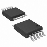
... Ordering Information Extended Type Number ATA8404-6DQY ATA8405-6DQY 9. Package Information TSSOP10 Package: TSSOP 10 (acc. to JEDEC Standard MO-187) Dimensions in mm Not indicated tolerances ± 0.05 0.5 nom 0 nom. ATA8404/ATA8405 [Preliminary] 18 Package Remarks TSSOP10 Pb-free TSSOP10 Pb-free 3 ±0.1 0. ±0.1 3.8 ±0.3 4.9 ±0.1 technical drawings ...
Page 19
... Revision No. 9136C-INDCO-10/09 9136B-INDCO-06/09 9136C–INDCO–10/09 ATA8404/ATA8405 [Preliminary] History Section 8 “Ordering Information” on page 18 changed Figure 1-1 “System Block Diagram” on page 1 changed Figure 4-7 “ASK Application Circuit” on page 12 changed Figure 4-8 “FSK Application Circuit” on page 13 changed ...
Page 20
... Disclaimer: The information in this document is provided in connection with Atmel products. No license, express or implied, by estoppel or otherwise, to any intellectual property right is granted by this document or in connection with the sale of Atmel products. EXCEPT AS SET FORTH IN ATMEL’S TERMS AND CONDI- TIONS OF SALE LOCATED ON ATMEL’S WEB SITE, ATMEL ASSUMES NO LIABILITY WHATSOEVER AND DISCLAIMS ANY EXPRESS, IMPLIED OR STATUTORY WARRANTY RELATING TO ITS PRODUCTS INCLUDING, BUT NOT LIMITED TO, THE IMPLIED WARRANTY OF MERCHANTABILITY, FITNESS FOR A PARTICULAR PURPOSE, OR NON-INFRINGEMENT ...