DEMOKITCRX14 STMicroelectronics, DEMOKITCRX14 Datasheet - Page 9
DEMOKITCRX14
Manufacturer Part Number
DEMOKITCRX14
Description
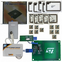
RFID EVALUATION KIT ISO14443-B
Manufacturer
STMicroelectronics
Type
Development kitr
Specifications of DEMOKITCRX14
Contents
CD-ROM, CRX14 Board, USB Transceiver, Samples and Documentation
Processor To Be Evaluated
CRX14
Interface Type
I2C
Operating Supply Voltage
5 V
For Use With/related Products
CRX14
Lead Free Status / RoHS Status
Contains lead / RoHS non-compliant
Other names
497-3704
Available stocks
Company
Part Number
Manufacturer
Quantity
Price
Company:

Part Number:
DEMOKITCRX14
Manufacturer:
HITACHI
Quantity:
340


CRX14 REGISTERS
The CRX14 chip coupler contains six volatile reg-
isters. It is entirely controlled, at both digital and
analog level, using the four registers listed below
and shown in
Table 2. CRX14 Control Registers
Parameter Register (00h)
The Parameter Register is an 8-bit volatile register
used to configure the CRX14, and thus, to custom-
ize the circuit behavior. The Parameter Register is
Table 3. Parameter Register Bits Description
Note: RFU = Reserved for Future Use.
b
b
b
b
b
b
b
b
00h
01h
02h
03h
04h
05h
Address
Bit
0
1
2
3
4
5
6
7
Parameter Register
Input/Output Frame Register
Authentication Register
Slot Marker Register
Frame Standard
RFU
Answer Frame Format
ASK Modulation Depth
Carrier Frequency
t
Answer delay watchdog
RFU
WDG
Parameter Register
Input/output Frame Register
Authenticate Register
Slot Marker Register
ST Reserved
ST Reserved
Table
Control
2.:
0
1
0
0
1
0
1
0
1
b5=0, b6=0: Watchdog time-out = 500µs to be used for read
b5=0, b6=1: Watchdog time-out = 5ms to be used for authentication
b5=1, b6=0: Watchdog time-out = 10ms to be used for write
b5=1, b6=1: Watchdog time-out = 309ms to be used for MCU timings
0
Value
RFU
Not used
Answer PICC Frames are delimited by SOF and EOF
Answer PICC Frames do not provide SOF and EOF delimiters
10% ASK modulation depth mode
RFU
13.56MHz carrier on RF OUT is OFF
13.56MHz carrier on RF OUT is ON
Not used
ISO14443 type-B frame management
1 Byte
36 Bytes
NA
1 Byte
NA
NA
Length
W
R
W
R
W
R
W
R
R and W ST Reserved. Must not be used
R and W ST Reserved. Must not be used
Access
The other 2 registers are located at addresses 04h
and 05h. They are “ST Reserved”, and must not
be used in end-user applications.
In the I²C protocol, all data Bytes are transmitted
Most Significant Byte first, with each Byte transmit-
ted Most significant bit first.
located at the I²C address 00h and it is accessible
in I²C Read and Write modes. Its default value,
00h, puts the CRX14 in standard ISO14443 type-
B configuration.
Set parameter register
Read parameter register
Store and send request frame to the PICC.
Wait for PICC answer frame
Transfer PICC answered frame data to Host
Start the Authentication process
Get the Authentication status
Launch the automated anti-collision process
from Slot_0 to Slot_15
Return data FFh
Description
Purpose
CRX14
9/40
Related parts for DEMOKITCRX14
Image
Part Number
Description
Manufacturer
Datasheet
Request
R

Part Number:
Description:
DEMO KIT M24LR-64-R
Manufacturer:
STMicroelectronics
Datasheet:

Part Number:
Description:
STMicroelectronics [RIPPLE-CARRY BINARY COUNTER/DIVIDERS]
Manufacturer:
STMicroelectronics
Datasheet:
Part Number:
Description:
STMicroelectronics [LIQUID-CRYSTAL DISPLAY DRIVERS]
Manufacturer:
STMicroelectronics
Datasheet:

Part Number:
Description:
BOARD EVAL FOR MEMS SENSORS
Manufacturer:
STMicroelectronics
Datasheet:
Part Number:
Description:
NPN TRANSISTOR POWER MODULE
Manufacturer:
STMicroelectronics
Datasheet:
Part Number:
Description:
TURBOSWITCH ULTRA-FAST HIGH VOLTAGE DIODE
Manufacturer:
STMicroelectronics
Datasheet:
Part Number:
Description:
Manufacturer:
STMicroelectronics
Datasheet:
Part Number:
Description:
DIODE / SCR MODULE
Manufacturer:
STMicroelectronics
Datasheet:
Part Number:
Description:
DIODE / SCR MODULE
Manufacturer:
STMicroelectronics
Datasheet:
Part Number:
Description:
Search -----> STE16N100
Manufacturer:
STMicroelectronics
Datasheet:
Part Number:
Description:
Search ---> STE53NA50
Manufacturer:
STMicroelectronics
Datasheet:
Part Number:
Description:
NPN Transistor Power Module
Manufacturer:
STMicroelectronics
Datasheet: