H-38-11 Bourns Inc., H-38-11 Datasheet - Page 36
H-38-11
Manufacturer Part Number
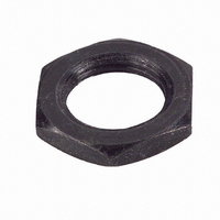
H-38-11
Description
HDWR NUT MOUNTING FOR ECW ENCODR
Manufacturer
Bourns Inc.
Type
Mounting Nutr
Series
Hr
Datasheet
1.H-37-2.pdf
(73 pages)
Specifications of H-38-11
Mounting Hole Size
9 mm
Features
Hardware indicated by shaded area is normally supplied with unit
Lead Free Status / RoHS Status
Lead free / RoHS Compliant
For Use With
ECW1DB24BC0024 - ENCODER DIGITAL CONT 24 CPRECW1JB24BC0024 - ENCODER DIGITAL CONT 24 CPR
Lead Free Status / Rohs Status
Lead free / RoHS Compliant


Application Notes
Encoders
General Application Information
Some general application information that should be
considered by designers:
• Encoders should be operated within the
• Care should be taken to provide adequate current
• Line drivers should be used when connecting to
• Care should be exercised when attaching the
• Exceeding the maximum
• Noise in the input power supply or the outputs of
recommended operating conditions. Electrostatic
discharge (ESD) precautions should be observed at
all times with non-contacting type encoders due to
possible damage to the internal electronics.
at the proper voltage to the encoder.
long leads, low-impedance loads, or capacitive
loads. Long leads on the output have an associated
capacitance, which can degrade high-frequency
signals.
encoder to a heat-generating device, such as a
motor, to prevent damage to the encoder. The
maximum temperature of the heat-generating
surface or the free ambient airspace, whichever is
greater, should be considered for selection of a
suitable encoder with adequate
operating temperature range.
mechanical speed of the encoder
may cause permanent damage to
the encoder. Exceeding the
maximum electrical speed may
result in incorrect data or signal
error.
an encoder may cause application problems. Some
of the common means of minimizing such noise are
grounding, twisted pairs, shielded or isolated leads,
and signal conditioning.
Signal Conditioning
Most applications where rotary contacting encoders
are used require the use of filters to condition the
digital output signal. Commercially available
integrated circuits (IC) or programmable logic chips
(PLC) provide the proper debounce and noise
filtration. Another alternative for signal conditioning
is software programming.
The use of debounce filters is recommended with all
contacting encoder models to avoid miscounts that
may be caused by wiper bounce. Our optical encoder
does not require the use of debounce filters due to
signal conditioning already provided by the custom
designed application specific integrated circuit
(ASIC) used in construction of the device.
Debounce filters such as the MC14490 Hex Contact
Bounce Eliminator manufactured by ON
Semiconductor can be used to eliminate encoder
contact bounce. The diagram in Figure 20 shows a
typical circuit configuration for encoder debounce
filtering. For additional information and
specification sheet for this device, visit ON
Semiconductor’s website at http://www.onsemi.com.
Note: This device was formerly manufactured by
Motorola.
Figure 20: Typical Debounce Circuit Configuration
35
Related parts for H-38-11
Image
Part Number
Description
Manufacturer
Datasheet
Request
R

Part Number:
Description:
Potentiometer Tools & Hardware Mounting Nut
Manufacturer:
Bourns Inc.
Datasheet:


Part Number:
Description:
HDWR LOCKWASHER FOR ECW ENCODER
Manufacturer:
Bourns Inc.
Datasheet:

Part Number:
Description:
PANEL SEAL ASSEMBLY, 3680 DIGI POT
Manufacturer:
Bourns Inc.
Datasheet:

Part Number:
Description:
COUNTING DIAL W/CLICK BRAKE
Manufacturer:
Bourns Inc.
Datasheet:

Part Number:
Description:
COUNTING DIAL 0-20 TURNS
Manufacturer:
Bourns Inc.
Datasheet:

Part Number:
Description:
ADJUSTMENT TOOL
Manufacturer:
Bourns Inc.
Datasheet:
Part Number:
Description:
Potentiometer Tools & Hardware Mounting Nut
Manufacturer:
Bourns Inc.
Datasheet: