H-38-11 Bourns Inc., H-38-11 Datasheet - Page 69
H-38-11
Manufacturer Part Number
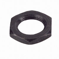
H-38-11
Description
HDWR NUT MOUNTING FOR ECW ENCODR
Manufacturer
Bourns Inc.
Type
Mounting Nutr
Series
Hr
Datasheet
1.H-37-2.pdf
(73 pages)
Specifications of H-38-11
Mounting Hole Size
9 mm
Features
Hardware indicated by shaded area is normally supplied with unit
Lead Free Status / RoHS Status
Lead free / RoHS Compliant
For Use With
ECW1DB24BC0024 - ENCODER DIGITAL CONT 24 CPRECW1JB24BC0024 - ENCODER DIGITAL CONT 24 CPR
Lead Free Status / Rohs Status
Lead free / RoHS Compliant


68
Glossary of Terms
Dielectric withstanding voltage
Effective electrical angle (EEA)
Encoder
End resistance
End voltage (non-wirewound)
End voltage (wirewound)
Equivalent noise resistance (ENR)
Ability to withstand under prescribed conditions, a
specified potential of a given characteristic
between the terminals of each cup and the exposed
conducting surfaces of the potentiometer, or
between the terminals of each cup and the
terminals of every other cup in the potentiometer
without exceeding a specified leakage current.
The total amount of angular input rotation over
which the output ratio actually varies.
A device that produces a digital output signal;
typically an incremental quadrature, binary, or
absolute output signal. This device eliminates the
need for analog-to-digital (A/D) signal
conversion.
The resistance measured between the wiper
terminal and end terminal with the shaft
positioned at the corresponding end of mechanical
travel.
The voltage between the wiper terminal and an
end terminal when the shaft is positioned at the
corresponding theoretical end point. End voltage is
expressed as a percent of the total applied voltage.
The voltage between the wiper terminal and an
end terminal when the shaft is positioned at the
corresponding end point. End voltage is expressed
as a percent of the total applied voltage.
The variation in resistance between the wiper and
a wirewound resistive element that occurs when
the wiper is energized with a specified current and
moved over the electrical travel in either direction
at a specified speed (does not include the effects of
roll-on or roll-off).
Gang
Gray code
Hybritron®
Incremental
Index
Independent linearity
Interpolation
Insulation resistance
An assembly of two or more cups on a common
operating shaft.
Binary code where only 1-bit changes logic state
from one angular position to the next (a.k.a.
Absolute code).
A hybrid element consisting of a wirewound
element with a conductive plastic coating; this
element will exhibit the stability characteristics of
a wirewound element with the long operational
life of a conductive plastic element.
The repetitive pattern of logic states (High, 1,
true/Low, 0 false) in the output signal of an
encoder occurring with each successive electrical
cycle of resolution.
The output signal of an index channel is normally
a single pulse per revolution. This output can be
used to indicate a “zero” or “home” position in the
shaft rotation. Adding an index channel to an
incremental encoder allows the encoder to provide
absolute position. (Also referred to as “Index
channel” and “Z-channel”)
The maximum deviation of the actual wiper
output function from a straight reference line with
its slope and position chosen to minimize
deviations.
A multiplication technique used to increase
encoder resolution.
The resistance to a specified impressed DC voltage
between the terminals of each cup and the exposed
conducting surfaces of the potentiometer, or
between the terminals of each cup and the
terminals of every other cup in the potentiometer,
under prescribed conditions.
Related parts for H-38-11
Image
Part Number
Description
Manufacturer
Datasheet
Request
R

Part Number:
Description:
Potentiometer Tools & Hardware Mounting Nut
Manufacturer:
Bourns Inc.
Datasheet:


Part Number:
Description:
HDWR LOCKWASHER FOR ECW ENCODER
Manufacturer:
Bourns Inc.
Datasheet:

Part Number:
Description:
PANEL SEAL ASSEMBLY, 3680 DIGI POT
Manufacturer:
Bourns Inc.
Datasheet:

Part Number:
Description:
COUNTING DIAL W/CLICK BRAKE
Manufacturer:
Bourns Inc.
Datasheet:

Part Number:
Description:
COUNTING DIAL 0-20 TURNS
Manufacturer:
Bourns Inc.
Datasheet:

Part Number:
Description:
ADJUSTMENT TOOL
Manufacturer:
Bourns Inc.
Datasheet:
Part Number:
Description:
Potentiometer Tools & Hardware Mounting Nut
Manufacturer:
Bourns Inc.
Datasheet: