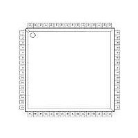
XRT5894IV-F Exar Corporation, XRT5894IV-F Datasheet - Page 8

XRT5894IV-F
Manufacturer Part Number
XRT5894IV-F
Description
IC LIU E1 QUAD 64TQFP
Manufacturer
Exar Corporation
Datasheet
1.XRT5894IVTR-F.pdf
(19 pages)
Specifications of XRT5894IV-F
Maximum Operating Temperature
+ 85 C
Maximum Power Dissipation
590 mW / 1240 mW
Minimum Operating Temperature
- 40 C
Mounting Style
SMD/SMT
Operating Supply Voltage
3.3 V / 5 V
Package / Case
TQFP-64
Supply Voltage Range
3.135V To 3.465V, 4.75V To 5.25
Power Dissipation Pd
1240mW
Operating Temperature Range
-40°C To +85°C
Digital Ic Case Style
TQFP
No. Of Pins
64
Filter Terminals
SMD
Rohs Compliant
Yes
Lead Free Status / RoHS Status
Lead free / RoHS Compliant
Lead Free Status / RoHS Status
Lead free / RoHS Compliant, Lead free / RoHS Compliant
Available stocks
Company
Part Number
Manufacturer
Quantity
Price
Company:
Part Number:
XRT5894IV-F
Manufacturer:
EXAR
Quantity:
1 558
Company:
Part Number:
XRT5894IV-F
Manufacturer:
Exar Corporation
Quantity:
10 000
Part Number:
XRT5894IV-F
Manufacturer:
EXAR/艾科嘉
Quantity:
20 000
Disabling Output Drivers
Output drivers may be individually disabled (hi-z output) by either of the following methods.
TRANSFORMER REQUIREMENTS
Note:
The same type 1:2 CT ratio device may be used at both receiver input and transmitter output.
The following transformers have been tested with the
XRT5894:
HALO type TG26-1205(package contains two 1 CT:2 CT ratio transformers)
Pulse type PE-65535 (1:2 CT ratio)
Transpower Technologies type TTI 7154-R (1:2 CT ratio)
Magnetic Supplier Information:
HALO Electronics, Inc.
P.O. Box 5826
Redwood City, CA 94063
Tel. (415) 568-5800
Fax. (415)568-6161
Pulse
Telecom Product Group
P.O. Box 12235
San Diego, CA 92112
Tel. (619) 674-8100
Fax. (619) 674-8262
Transpower Technologies, Inc.
24 Highway 28, Suite 202
Crystal Bay, NV 89402--0187
Tel. (702) 831--0140
Fax. (702) 831--3521
XRT5894
1. Either connect the transmit data inputs TXPOS
Rev. 1.10
Table 1. Input Transformer Requirements
and TXNEG for the channel to be disabled to a log-
ic 1 source (VCC), or allow them to float (inputs
have internal pull--up resistors).
Turns Ratio
1:2 CT
Line Impedance
75W or 120W
8
2. Connect TXCLK for the channel to be disabled to
Table 2. Output Transformer Requirements
logic 0 source (Ground), and also apply data to the
TXPOS and TXNEG inputs of that channel.
Turns Ratio
1:2
Line Impedance
75W or 120W


