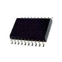
73S8014RN-IL/F Maxim Integrated Products, 73S8014RN-IL/F Datasheet - Page 13

73S8014RN-IL/F
Manufacturer Part Number
73S8014RN-IL/F
Description
IC SMART CARD 7816 EMV 20-SOIC
Manufacturer
Maxim Integrated Products
Datasheet
1.73S8014RN-DB.pdf
(28 pages)
Specifications of 73S8014RN-IL/F
Controller Type
Smart Card Interface
Voltage - Supply
2.7 V ~ 5.5 V
Operating Temperature
-40°C ~ 85°C
Mounting Type
Surface Mount
Package / Case
20-SOIC (0.300", 7.50mm Width) Exposed Pad
Lead Free Status / RoHS Status
Lead free / RoHS Compliant
Current - Supply
-
Interface
-
Lead Free Status / Rohs Status
Lead free / RoHS Compliant
Available stocks
Company
Part Number
Manufacturer
Quantity
Price
Company:
Part Number:
73S8014RN-IL/F
Manufacturer:
Maxim
Quantity:
234
Company:
Part Number:
73S8014RN-IL/F
Manufacturer:
TI
Quantity:
15
DS_8014RN_014
73S8014RN Data Sheet
3 Applications Information
This section provides general usage information for the design and implementation of the 73S8014RN. The
documents listed in
Related Documentation
provide more detailed information.
3.1 Example 73S8014RN Schematics
Figure 3
shows a typical application schematic for the implementation of the 73S8014RN.
Note that minor changes may occur to the reference material from time to time and the reader is encouraged to
contact Teridian for the latest information.
3.2 NDS Precautions
Preliminary testing against the NDS specification has found that the coupled noise level on the I/O signal may
approach the maximum NDS limits. Teridian recommends adding capacitor footprints on the CLK, RST and I/O
signals for addition of small capacitors to filter system noise if needed. These footprints should be added at or
near the smart card connector interface. A typical value of 27pF has been found to reduce the noise to
acceptable levels where the noise is an issue. In addition, Teridian recommends the addition of a 0 ohm series
resistor in the CLK path. If the CLK output is found to generate too much system noise, a small resistor can be
substituted to create a small RC network to slow the CLK edges and reduce the CLK noise to the rest of the
system. The amount of the noise being generated from the CLK signal depends on many factors including; board
layout and component placement, clock input source, distance between 8014 and the card interface, etc. Lastly,
some isolation between the CLK signal should be provided against all other system signals, especially the RST
and I/O signals.
Rev. 1.0
13


