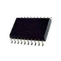
73S8014RN-IL/F Maxim Integrated Products, 73S8014RN-IL/F Datasheet - Page 16

73S8014RN-IL/F
Manufacturer Part Number
73S8014RN-IL/F
Description
IC SMART CARD 7816 EMV 20-SOIC
Manufacturer
Maxim Integrated Products
Datasheet
1.73S8014RN-DB.pdf
(28 pages)
Specifications of 73S8014RN-IL/F
Controller Type
Smart Card Interface
Voltage - Supply
2.7 V ~ 5.5 V
Operating Temperature
-40°C ~ 85°C
Mounting Type
Surface Mount
Package / Case
20-SOIC (0.300", 7.50mm Width) Exposed Pad
Lead Free Status / RoHS Status
Lead free / RoHS Compliant
Current - Supply
-
Interface
-
Lead Free Status / Rohs Status
Lead free / RoHS Compliant
Available stocks
Company
Part Number
Manufacturer
Quantity
Price
Company:
Part Number:
73S8014RN-IL/F
Manufacturer:
Maxim
Quantity:
234
Company:
Part Number:
73S8014RN-IL/F
Manufacturer:
TI
Quantity:
15
3.5
The card power supply is internally provided by the LDO regulator, and controlled by the digital ISO-7816-3
sequencer.
3.6
The 73S8014RN devices have an on-chip oscillator that can generate the smart card clock using an external
crystal (connected between the pins XTALIN and XTALOUT) to set the oscillator frequency. When the clock
signal is available from another source, it can be connected to the pin XTALIN, and the pin XTALOUT should be
left unconnected. The 73S8014RN is capable of generating the 4.5, 6.75 and 13.5MHz NDS clock frequencies
using a crystal or external source set at 27MHz.
The card clock frequency may be chosen between 4 different division rates, defined by digital inputs CLKDIV 1
and CLKDIV 2, as per the following table:
3.7 Activation Sequence
The 73S8014RN smart card interface ICs have an internal 10ms delay on the application of V
V
low to activate the card. In order to initiate activation, the card must be present; there can be no V
The following steps show the activation sequence and the timing of the card control signals when the system
controller sets CMDVCC low while the RSTIN is low:
16
DDF
-
-
-
-
-
. No activation is allowed during this 10ms period. The CMDVCC (edge triggered) signal must then be set
Card Power Supply
On-Chip Oscillator and Card Clock
CMDVCC is set low at t
V
the end of t
at t
Turn I/O to reception mode at t
CLK is applied to the card at t
RST is a copy of RSTIN after t
CC
1
, the OFF goes low to report a fault to the system controller, and V
will rise to the selected level and then the internal V
CMDVCC
t
t
t
1
2
3
RSTIN
VCC
RST
CLK
= 0.510 ms (timing by 1.5MHz internal oscillator)
= 1.5μs, I/O goes to reception state
= >0.5μs, CLK starts, RST to become the copy of RSTIN
I/O
Figure 4: Activation Sequence – RSTIN Low When CMDVCC Goes Low
1
. In normal operation, the voltage V
CLKDIV1
0
0
1
1
0
.
t
0
3
3
.
CLKDIV2
2
.
.
0
1
0
1
t
1
1/6
¼ XTALIN
½ XTALIN
XTALIN
CC
CLK
XTALIN
to the card becomes valid before t
t
CC
2
control circuit checks the presence of V
t
3
Max XTALIN
27MHz
27MHz
20MHz
27MHz
CC
to the card is shut off.
1
DD
. If V
where V
DD
CC
fault.
is not valid
DD
Rev. 1.0
CC
>
at


