EA EDIPTFT43-ATP ELECTRONIC ASSEMBLY, EA EDIPTFT43-ATP Datasheet - Page 8
EA EDIPTFT43-ATP
Manufacturer Part Number
EA EDIPTFT43-ATP
Description
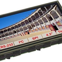
TFT Displays & Accessories 4.3 TFT w/ Touch w/ Intellegence
Manufacturer
ELECTRONIC ASSEMBLY
Datasheet
1.EA_EDIPTFT43-A.pdf
(28 pages)
Specifications of EA EDIPTFT43-ATP
Background Color
White
Interface Type
RS-232, I2C, SPI-Bus
Maximum Operating Temperature
+ 70 C
Minimum Operating Temperature
- 20 C
Operating Current
180 mA
Product
Displays
Supply Voltage
5 V
Touch Panel
Touch Panel
Pixel Density
480 x 272
Module Size (w X H X T)
107 mm x 71 mm x 12 mm
Backlighting
LED
Lead Free Status / RoHS Status
Lead free / RoHS Compliant


EA eDIPTFT43-A
Page 8
ANALOGUE INPUT AIN1AUND AIN2 (PIN 23+24)
For analogue measurement 2 inputs with a range of 0..+5V are available. Each input is grounded
(GND) and DC impedance is 1MΩ. Please make sure that only positive voltages will be supplied
there. Internal resolution is 10 Bit, equal to a 3-digit DVM modul. Linearity (after adjustment) is around
0.5%.
Adjustment
Analogue inputs are not calibrated when shipped out. A procedure for adjustment may be like that:
1.) Put a well known voltage within a range of 3-5V to analogue input (example: 4,0V, AIN1)
2.) Run command for calibration (see page 15). Example: "ESC V @ 1 4000".
Measurement
Each input query can be done via serial interface or directly shown on display (as digits or bargraph
in various colors and sizes).
Best way for direct visualisation are Process-macros or one of Analogue-macros (e.g. starting at every
voltage change, or above/below a limit).
Both input lines are scaleable from 0 to ±9999.9. Scaling will be done via definition at 2 voltages
„value1=string1;value2=string2“ (see table on page 15).
DIGITAL INPUT AN OUTPUT
The EA eDIPTFT43-A is featured with 8 digital input and 8 digital output lines (5V CMOS level,
grounded).
8 outputs
Each line can be controlled individually using the
"ESC Y W" command. A maximum current of 10mA can
be switched per line. This give the opportunity to drive a
low power LED in direct way. To source higher current
please use an external transistor.
8 inputs
Each input provides an internal 20..50 kΩ pull-up resistor, so it is possible to
connect a key or switch directly between input and GND. The inputs can be
queried and evaluated directly via the serial interface ("ESC Y R").
In addition to that every port change may start an individual port - or bit- macro.
The command "ESC Y A 0" disables automatic port query.
Port Macro:
when the 8 lines are combined, up to 256 port macros can thus be addressed.
Bit Macro:
Bit Macro 1..8 will be started when one of the lines 1..8 changes to low (falling edge).
Bit Macro 9..16 will be started when one of these lines is gong to high (rising edge).
It is possible to change the assignment between Bitmacro and intput with command ‘ESC Y D n1 n2
n3’ (since firmware V1.1, see page 17).
If both macros (Port and Bit macro) are defined, every change will start Bit Macro first and then Port
Makro. If there's no macro defined, port status will be sent to sendbuffer.
Note: The logic circuitry is designed for slow operations; in other words, more than 3 changes per
second cannot be easily executed.
ELECTRONIC ASSEMBLY reserves
the right to change specifications
without prior notice. Printing and
typographical
errors
reserved.
Related parts for EA EDIPTFT43-ATP
Image
Part Number
Description
Manufacturer
Datasheet
Request
R

Part Number:
Description:
Display Development Tools StrEval Kit Blk-Wht w/ Intf Exp and CD
Manufacturer:
ELECTRONIC ASSEMBLY
Datasheet:

Part Number:
Description:
Display Modules & Development Tools Starter/Demoboard Windows USB For DOGM
Manufacturer:
ELECTRONIC ASSEMBLY

Part Number:
Description:
Display Modules & Development Tools Starter/Demoboard DOGM/ Windows USB
Manufacturer:
ELECTRONIC ASSEMBLY
Datasheet:

Part Number:
Description:
LCD Character Display Modules 4x20 Yellow/Green RS-232 Interface
Manufacturer:
ELECTRONIC ASSEMBLY
Part Number:
Description:
LCD Character Display Modules 4x20 Blue-White RS-232 Interface
Manufacturer:
ELECTRONIC ASSEMBLY
Part Number:
Description:
LCD Character Display Modules 2x16 Yellow/Green RS-232 Interface
Manufacturer:
ELECTRONIC ASSEMBLY

Part Number:
Description:
LCD Character Display Modules STN(+) Reflective Yel/Grn Background
Manufacturer:
ELECTRONIC ASSEMBLY
Datasheet:

Part Number:
Description:
LCD Character Display Modules STN(-) Transmissive Blue Background
Manufacturer:
ELECTRONIC ASSEMBLY
Datasheet:

Part Number:
Description:
LCD Character Display Modules FSTN(-) Transmissive Black Background
Manufacturer:
ELECTRONIC ASSEMBLY
Datasheet:
Part Number:
Description:
LCD Character Display Modules Yel/Green Contrast Yl/Grn LED Backlight
Manufacturer:
ELECTRONIC ASSEMBLY
Datasheet:

Part Number:
Description:
LCD Touch Panels Touchpanel Analog for DOGM128-6
Manufacturer:
ELECTRONIC ASSEMBLY
Datasheet:
Part Number:
Description:
LCD Touch Panels Touchpanel Analog For DOGS102
Manufacturer:
ELECTRONIC ASSEMBLY
Datasheet:
Part Number:
Description:
LCD Touch Panels Touchpanel Analog For DOGXL160
Manufacturer:
ELECTRONIC ASSEMBLY
Datasheet:
Part Number:
Description:
LCD Touch Panels Touchpanel Analog For DOG-L128-6
Manufacturer:
ELECTRONIC ASSEMBLY
Datasheet:

Part Number:
Description:
LED Displays Bezel 017-xx Series 75.0x24.2/ 91.0x36.4
Manufacturer:
ELECTRONIC ASSEMBLY
Datasheet: