LQ043T1DG01 Sharp Microelectronics, LQ043T1DG01 Datasheet - Page 19
LQ043T1DG01
Manufacturer Part Number
LQ043T1DG01
Description
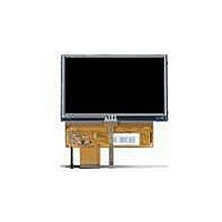
TFT Displays & Accessories 4.3 480x272 ASV TFT LCD
Manufacturer
Sharp Microelectronics
Datasheet
1.LQ043T1DG01.pdf
(26 pages)
Specifications of LQ043T1DG01
Background Color
Normally White
Diagonal
4.3 in
Maximum Operating Temperature
+ 85 C
Minimum Operating Temperature
- 30 C
Operating Temperature Range
- 30 C to + 85 C
Product
Displays
Touch Panel
Touch Panel
Pixel Density
480 x 272
Module Size (w X H X T)
105.5 mm x 67.2 mm x 5.05 mm
Backlighting
9 x LED
Lead Free Status / RoHS Status
Lead free / RoHS Compliant
Available stocks
Company
Part Number
Manufacturer
Quantity
Price
Company:

Part Number:
LQ043T1DG01
Manufacturer:
SHARP
Quantity:
1 000


10. Touch panel characteristics
11. Mechanical characteristics
11-1) FPC (for LCD panel) characteristics
11-2) Design guidance for touch panel (T/P)
Parameter
Input voltage
Resistor between terminals (XL-XR)
Resistor between terminals (YU-YD)
Line linearity (X direction)
Line linearity (Y direction)
Insulation resistance
Minimum tension for detecting
11-2-1) Example of housing design
11-2-2) Mounting on display and housing bezel
(1) Specific connector: FH12A-40S-0.5SH(55) (HIROSE)
(2) Bending endurance of the bending slits portion
(1) If a consumer will put a palm on housing in normal usage, care should be taken as follows.
(3) Insertion a cushion material is recommended.
(4) The cushion material should be limited just on the busbar insulation paste area.
(5) There is one where a resistance film is left in the T/P part of the end of the pole.
(4) Top layer, PET, dimension is changing with environmental temperature and humidity.
(5) The input to the Touch panel sometimes distorts touch panel itself.
(2) Keep the gap, for example 0.3 to 0.7mm, between bezel edge and T/P surface.
(1) In all cases, the T/P should be supported from the backside of the Plastic.
(2) Do not to use an adhesive-tape to bond it on the front of T/P and hang it to the housing bezel.
(3) Never expand the T/P top layer (PET-film) like a balloon by internal air pressure.
If it is over the transparent insulation paste area, a ”short” may be occurred.
Design to keep insulation from the perimeter to prevent from mis-operation and so on.
Avoid a stress from housing bezel to top layer, because it may cause “waving”.
The life of the T/P will be extremely short.
The reason is to avoid the bezel edge from contacting T/P surface that may cause a “short”
with bottom layer (See Fig.3)
Cushion material
Transparent
Insulation Paste
(=Cushion Area)
Insulation metal
No line of the FPC is broken for the bending test (Bending radius=0.6mm and
angle=90°) in 30 cycles.
PET Film
Glass
material
Housing
Min.
200
160
20
-
-
-
-
Response Area
Prohibition Area
Typ.
463
291
5.0
-
-
-
-
Max.
0.88
900
640
7.0
1.5
1.5
-
Unit
MΩ
%
%
LCY-W-06602A Page 16 of 22
Ω
Ω
V
N
Electrode
Provisional
specification
at DC25V
Layer
0.3
~0.7mm
Remark
Related parts for LQ043T1DG01
Image
Part Number
Description
Manufacturer
Datasheet
Request
R

Part Number:
Description:
IC FLASH 32MBIT 110NS 56SSOP
Manufacturer:
Sharp Microelectronics
Datasheet:

Part Number:
Description:
IC FLASH 16MBIT 100NS 56TSOP
Manufacturer:
Sharp Microelectronics
Datasheet:

Part Number:
Description:
IC FLASH 64MBIT 120NS 56TSOP
Manufacturer:
Sharp Microelectronics
Datasheet:

Part Number:
Description:
IC FLASH 16MBIT 90NS 48TSOP
Manufacturer:
Sharp Microelectronics
Datasheet:
Part Number:
Description:
IC SRAM 16KBIT 100NS 24DIP
Manufacturer:
Sharp Microelectronics
Datasheet:
Part Number:
Description:
IC SRAM 16KBIT 100NS 24SOP
Manufacturer:
Sharp Microelectronics
Datasheet:
Part Number:
Description:
IC SRAM 64KBIT 100NS 28DIP
Manufacturer:
Sharp Microelectronics
Datasheet:
Part Number:
Description:
IC SRAM 64KBIT 100NS 28SOP
Manufacturer:
Sharp Microelectronics
Datasheet:
Part Number:
Description:
IC SRAM 64KBIT 100NS 28SOP
Manufacturer:
Sharp Microelectronics
Datasheet:
Part Number:
Description:
IC SRAM 256KBIT 70NS 28DIP
Manufacturer:
Sharp Microelectronics
Datasheet:
Part Number:
Description:
IC FLASH 8MBIT 90NS 48TSOP
Manufacturer:
Sharp Microelectronics
Datasheet:
Part Number:
Description:
IC FLASH 8MBIT 85NS 40TSOP
Manufacturer:
Sharp Microelectronics
Datasheet:
Part Number:
Description:
IC FLASH 8MBIT 85NS 40TSOP
Manufacturer:
Sharp Microelectronics
Datasheet:
Part Number:
Description:
IC FLASH 16MBIT 90NS 48TSOP
Manufacturer:
Sharp Microelectronics
Datasheet:
Part Number:
Description:
IC FLASH 16MBIT 70NS 56TSOP
Manufacturer:
Sharp Microelectronics
Datasheet: