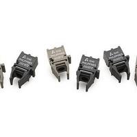
HFBR-2521ETZ Avago Technologies US Inc., HFBR-2521ETZ Datasheet - Page 8

HFBR-2521ETZ
Manufacturer Part Number
HFBR-2521ETZ
Description
Fiber Optic Transmitters, Receivers, Transceivers Versatile Link Horiz
Manufacturer
Avago Technologies US Inc.
Series
Versatile Linkr
Datasheet
1.HFBR-1527ETZ.pdf
(14 pages)
Specifications of HFBR-2521ETZ
Maximum Forward Current
80 mA
Maximum Power Dissipation
40 mW
Operating Voltage
7 V
Transmission Distance
43 m
Product
Receiver
Data Rate
5 MBd
Wavelength
660 nm
Diode Capacitance
86 pF
Maximum Rise Time
20 ns
Maximum Fall Time
20 ns
Pulse Width Distortion
40 ns
Maximum Output Current
250 uA
Operating Supply Voltage
7 V
Maximum Operating Temperature
+ 85 C
Minimum Operating Temperature
- 40 C
Data Transmission Distance
38m
Wavelength Typ
660nm
Leaded Process Compatible
Yes
Peak Reflow Compatible (260 C)
Yes
Rohs Compliant
Yes
Voltage - Supply
4.75 V ~ 5.25 V
Power - Minimum Receivable
-21.6dBm
Current - Supply
6.2mA
Applications
General Purpose
Lead Free Status / RoHS Status
Lead free / RoHS Compliant
Available stocks
Company
Part Number
Manufacturer
Quantity
Price
Company:
Part Number:
HFBR-2521ETZ
Manufacturer:
ST
Quantity:
21 400
Part Number:
HFBR-2521ETZ HFBR-1521ETZ
Manufacturer:
AVAGO/安华高
Quantity:
20 000
Transmitter Electrical/Optical Characteristics
Notes:
1. Optical power measured at the end of 0.5 m of 1 mm diameter POF (NA = 0.5) with a large area detector.
2. Optical power, P (dBm) = 10 Log [P(PW)/1000 PW].
3. Rise and fall times are measured with a voltage pulse driving the transmitter driver IC (75451). A wide bandwidth optical to electrical waveform
Figure 7. Typical forward voltage vs. drive current
8
Parameter
Transmitter Output
Output Optical Power
Temperature Coefficient
Peak Emission
Wavelength
Forward Voltage
Forward Voltage
Temperature Coefficient
Effective Diameter
Reverse Input Breakdown
Voltage
Diode Capacitance
Rise Time
Fall Time
Optical Power
analyzer, terminated to a 50 : input of a wide bandwidth oscilloscope, is used for this response time measurement.
1.75
1.65
1.55
1.45
1.8
1.7
1.6
1.5
1.4
1
I
Fdc
- TRANSMITTER DRIVE CURRENT (mA)
10
'P
'V
Symbol
O
V
C
P
T
V
F
D
t
t
PK
BR
F
O
r
T
/'T
/'T
f
-16.8
-14.3
-40° to 85° C unless otherwise specified.
Min.
1.43
5.0
-40° C
25° C
85° C
100
Typ.
-0.85
-1.37
1.67
11.0
660
86
20
20
1
[5]
Figure 8. Normalized typical output power vs. drive current
-10
-15
-20
Max.
2.05
-7.1
-8.0
-5
5
0
1
mV/°C
Units
%/°C
dBm
dBm
mm
nm
pF
ns
ns
V
V
I
Fdc
- TRANSMITTER DRIVE CURRENT (mA)
I
I
I
I
T
V
10% to 90%,
I
Fdc
Fdc
Fdc
Fdc
A
F
F
= 60 mA
= 25° C
= 0, f = MHz
= 60 mA
= 60 mA, 25° C
= 60 mA
= 10 PA,
Conditions
10
Notes 1, 2
Note 3
Fig. 7
-40° C
Ref.
25° C
85° C
100


