AGLP-EVAL-KIT Actel, AGLP-EVAL-KIT Datasheet - Page 25
AGLP-EVAL-KIT
Manufacturer Part Number
AGLP-EVAL-KIT
Description
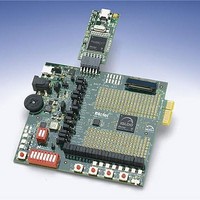
MCU, MPU & DSP Development Tools IGLOO PLUS Starter Kit
Manufacturer
Actel
Datasheet
1.AGLP-EVAL-KIT.pdf
(62 pages)
Specifications of AGLP-EVAL-KIT
Processor To Be Evaluated
CSG289
Interface Type
USB, JTAG
Operating Supply Voltage
1.2 V to 1.5 V
Lead Free Status / RoHS Status
Lead free / RoHS Compliant


Battery
Potentiometer and Voltage-Sweep
IGLOO PLUS Starter Kit User’s Guide
In addition to the power brick and USB, this board provides the option to power-up via battery. No battery casing is
provided on the board. Jumpers should be set correctly to select the option of either powering through a wall/USB or
through batteries hooked up externally. To provide a 3 V input source from battery, two AA Alkaline cells may be used.
A 2-pin jumper for VBAT and GND must be provided to the input of the main regulator to give the option of either
powering through a wall/USB or powering through batteries hooked up externally.
A potentiometer is located on the left hand side of the board to provide the voltage-sweep function to sweep V
(Figure
how the FPGA can operate successfully even if V
V
headers
CC
for battery operations. When using the potentiometer, you should also monitor the V
3-3). One primary function of the potentiometer is to show battery operation on the IGLOO PLUS device and
(Figure 3-4 on page
V
V
CCI
2.5 V
CCI
3.3 V
-Sweep
-Sweep
Figure 3-2 · Battery Header and Power Input Schematics
26) to make sure it does not go beyond the specified value.
V
Figure 3-3 · Current Measurement Headers
CCI
1x2_100MIL
1x2_100MIL
J7
J7
BATTERY
BATTERY
-Sweep
1.5 V
CC
1
2
experiences a drop in voltage. You can measure the lowest possible
3.3 V
3.3 V
3.3 V
3.3 V
BAT
Measurement
Current
EXTERNAL
BATTERY
SOURCE
IGLOO PLUS
VCCI_0
VCCI_1
VCCI_2
VCCI_3
V
V
V
CC
JTAG
PUMP
CC
via current measurement
CC
Battery
25
Related parts for AGLP-EVAL-KIT
Image
Part Number
Description
Manufacturer
Datasheet
Request
R

Part Number:
Description:
MCU, MPU & DSP Development Tools Silicon Sculptor Programming Mod
Manufacturer:
Actel
Part Number:
Description:
MCU, MPU & DSP Development Tools InSystem Programming ProASICPLUS Devices
Manufacturer:
Actel
Part Number:
Description:
Programming Socket Adapters & Emulators PQ160 Module
Manufacturer:
Actel
Part Number:
Description:
Programming Socket Adapters & Emulators Axcelerator Adap Module Kit
Manufacturer:
Actel
Part Number:
Description:
Programming Socket Adapters & Emulators Evaluation
Manufacturer:
Actel
Part Number:
Description:
Programming Socket Adapters & Emulators AFDX Solutions
Manufacturer:
Actel
Part Number:
Description:
Programming Socket Adapters & Emulators SILICON SCULPTOR ADAPTER MODULE
Manufacturer:
Actel
Datasheet:
Part Number:
Description:
Programming Socket Adapters & Emulators Axcelerator Adap Module Kit
Manufacturer:
Actel
Part Number:
Description:
Programming Socket Adapters & Emulators Evaluation
Manufacturer:
Actel
Part Number:
Description:
Programming Socket Adapters & Emulators Silicon Sculptor Software
Manufacturer:
Actel
Part Number:
Description:
Programming Socket Adapters & Emulators InSystem Programming ProASICPLUS Devices
Manufacturer:
Actel
Part Number:
Description:
Programming Socket Adapters & Emulators Evaluation
Manufacturer:
Actel
Part Number:
Description:
Programming Socket Adapters & Emulators Axcelerator Adap Module Kit
Manufacturer:
Actel
Part Number:
Description:
Programming Socket Adapters & Emulators Axcelerator Adap Module Kit
Manufacturer:
Actel
Part Number:
Description:
Programming Socket Adapters & Emulators Axcelerator Adap Module Kit
Manufacturer:
Actel