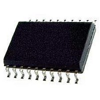
KX1400EW Keterex, KX1400EW Datasheet - Page 19

KX1400EW
Manufacturer Part Number
KX1400EW
Description
Audio D/A Converter ICs KX1400 Audio Playback IC
Manufacturer
Keterex
Datasheet
1.KX1400EW.pdf
(29 pages)
Specifications of KX1400EW
Resolution
12 bit
Operating Supply Voltage
2.7 V to 5.5 V
Operating Temperature Range
- 40 C to + 85 C
Maximum Power Dissipation
120 mW
Mounting Style
SMD/SMT
Number Of Dac Outputs
2
Power Consumption
320 mW
Supply Current
50 mA
Thd Plus Noise
40 dB
Package / Case
SOIC-20
Lead Free Status / RoHS Status
Lead free / RoHS Compliant
MCU host interface or as part of a phrase processed from external memory. Stand-by Mode is exited by
performing a device reset or on the next falling edge of the
Stand-by mode is entered by setting the Stand-by Option bit when issuing the Stop command via the
by mode, the first rising edge of the SCL clock signal must be delayed at least 500 ns after the
is asserted when using the Host MCU interface. Refer to Section 8.2 for detailed information on the use
of the Stop command and the Stand-by mode option.
7. EXAMPLE APPLICATION CIRCUITS
7.1. Stand-Alone Operation
Following is an example circuit with the KX1400 operating in stand-alone mode and optional LEDs
connected to general purpose outputs. The LEDs are controlled with Set Outputs commands embedded
in audio data played from the attached serial memory. A single audio phrase is played each time the
push-button switch connected to
+VDD
Figure 7.1. KX1400 in Stand-alone Operation
RST
CLKOUT
CS
SCL
SDI
BUSY
RDY
MODE
MSIZE
GND
VDD
VDD2
RST
¯¯¯
pin is pushed/released.
GPO1
SPO+
MCLK
GPO2
MSSL
SPO-
MISO
MOSI
CS
¯¯
Serial
Memory
CS
SO
SCK
SI
KX1400 Audio Playback IC
signal. If using the
Optional
GND
VCC
CS
¯¯
signal to exit Stand-
CS
¯¯
signal
19


