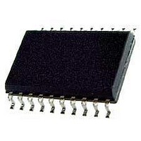
KX1400EW Keterex, KX1400EW Datasheet - Page 27

KX1400EW
Manufacturer Part Number
KX1400EW
Description
Audio D/A Converter ICs KX1400 Audio Playback IC
Manufacturer
Keterex
Datasheet
1.KX1400EW.pdf
(29 pages)
Specifications of KX1400EW
Resolution
12 bit
Operating Supply Voltage
2.7 V to 5.5 V
Operating Temperature Range
- 40 C to + 85 C
Maximum Power Dissipation
120 mW
Mounting Style
SMD/SMT
Number Of Dac Outputs
2
Power Consumption
320 mW
Supply Current
50 mA
Thd Plus Noise
40 dB
Package / Case
SOIC-20
Lead Free Status / RoHS Status
Lead free / RoHS Compliant
8.11. Play ADPCM (From External Memory)
Description: When used within a phrase to be processed from external memory, the Play ADPCM
8.12. Set Clock
Description: The Set Clock command is used to enable/disable the Clock Output feature and to specify
Encoding:
Encoding:
Options: Bit 4: ADPCM Reset
Options: Bit 6: Clock-out Stop State
Length: 16 Bits
Length: 24 or 32 Bits
Type: Audio
Type: Control
Data: Bits 31-8: Number of Bytes
This is a 4-bit, 8 kHz IMA ADPCM audio sample. Sample 2 is processed after Sample 1.
command instructs the KX1400 to retrieve a specified number of IMA ADPCM audio
samples from external memory to be decoded and sent to the Digital Audio Processor at
the appropriate sample rate. The ADPCM sample data is expected to be organized in
external memory two samples per byte. The sample stored in the low-order nibble (least-
significant 4 bits) is played first.
Note: The KX1400 will ignore all incoming commands while executing a Play ADPCM
command from external memory, including the Stop command. To abort a Play ADPCM
command from external memory, a hardware reset must be performed.
Setting this bit to a logic one resets the ADPCM decoder state. The ADPCM decoder must
be reset at the beginning of each new ADPCM sequence.
When using an external memory with 24-bit addressing (MSIZE =1) bits 31-8 represent the
number of sequential bytes that will be retrieved and processed as 4-bit, 8 kHz IMA
ADPCM data. ADPCM data is packed two samples per byte; therefore, this number is
calculated as the number of ADPCM samples divided by two. (The number of ADPCM
samples must be even.)
If the external memory uses 16-bit addressing (MSIZE = 0) bits 23-8 are used for the 16-bit
byte count and the next following byte of memory (bits 31-24) is the first byte of ADPCM
data.
the frequency of the clock-out signal.
Clock-out Disable
Number of Bytes
Bit 7
Bits 31-8
Clock-out Stop State
Bits 7-5
Unused
Bit 6
KX1400 Audio Playback IC
ADPCM Reset
Bit 4
Clock Divisor
Bits 5-4
Bits 3-0
1010
Bits 3-0
1100
27


