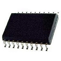
KX1400EW Keterex, KX1400EW Datasheet - Page 8

KX1400EW
Manufacturer Part Number
KX1400EW
Description
Audio D/A Converter ICs KX1400 Audio Playback IC
Manufacturer
Keterex
Datasheet
1.KX1400EW.pdf
(29 pages)
Specifications of KX1400EW
Resolution
12 bit
Operating Supply Voltage
2.7 V to 5.5 V
Operating Temperature Range
- 40 C to + 85 C
Maximum Power Dissipation
120 mW
Mounting Style
SMD/SMT
Number Of Dac Outputs
2
Power Consumption
320 mW
Supply Current
50 mA
Thd Plus Noise
40 dB
Package / Case
SOIC-20
Lead Free Status / RoHS Status
Lead free / RoHS Compliant
noise shaping Digital Audio Processor (DAP). It can also generate audio data for 4096 different single-
of operation is determined by the state of the MODE pin as the KX1400 exits reset. Setting the MODE
pin to a logic low state causes the KX1400 to operate in stand-alone mode. Setting MODE to logic high
In host-controlled mode, a host MCU is connected to the KX1400 using a 4 or 5-wire host interface.
Using this interface, the host can send audio data directly to the audio processor, select one of 4096
different phrases to play from an external memory, play tones using the on-chip tone generator, or
change the configuration of the KX1400.
KX1400 Audio Playback IC
5. OPERATING CHARACTERISTICS
Specifications are for T
fosc
Δf
f
THD
P
RST
RST
T
T
6. FUNCTIONAL DESCRIPTION
Using a fixed 8 KHz sample rate, the KX1400’s audio processor decodes uncompressed 12-bit PCM or 4-
bit IMA Adaptive Pulse Code Modulation (ADPCM) audio data and sends it to an on-chip, second-order
frequency tones. The DAP’s output is connected to an on-chip class-D amplifier stage which provides
differential outputs suitable for directly driving an external 8Ω speaker.
6.1. Operational Modes
The KX1400 supports two modes of operation: stand-alone mode and host-controlled mode. The mode
configures the KX1400 to operate in host-controlled mode.
6.1.1. Stand-alone Mode
In stand-alone mode, no host MCU is required. The KX1400 is connected directly to an external serial
memory. On exit from a reset, the KX1400 processes the first phrase (command and data sequence)
from external memory. In stand-alone mode, control of the KX1400 can be implemented as simply as
relying on power-on-reset events or connecting a switch to the
alone operation, the
6.1.2. Host-controlled Mode
8
¯¯¯
¯¯¯
SYMBOL
SW
OUT
CLKOUTH
CLKOUTL
OSC
DELAY
MI
N
Internal Oscillator Frequency
Internal Oscillator Frequency
Variation
Output Switching Frequency
Total Harmonic Distortion
Maximum Output Power
Delay From
Execution of First Command
Minimum
Generate a System Reset
Clock Out High Time
Clock Out Low Time
PARAMETER
CS
¯¯
RST
¯¯¯
A
pin should be connected to VDD and the SCL and SDI pins connected to ground.
= -20
RST
¯¯¯
Low Time to
°
High
C to +70
to
°
C, VDD = 2.7V to 5.5V unless otherwise specified.
VDD=3.3V, 8Ω Load
2.7V ≤ VDD ≤ 3.6V
2.7V ≤ VDD ≤ 5.5V
VDD=5V, 8Ω Load
Fclkout = 8.2MHz
VDD = 3.3V, T =
250Hz tone into
CONDITIONS
8Ω Load
25°C
RST
¯¯¯
8.07
MIN
100
pin of the KX1400. Note: In stand-
40
40
-1
-1
8.192
TYP
256
120
320
40
MAX
8.32
+1
+3
20
80
80
UNITS
MHz
kHz
mW
mW
dB
µS
ns
ns
ns
%
%


