TSL2561T TAOS, TSL2561T Datasheet - Page 11
TSL2561T
Manufacturer Part Number
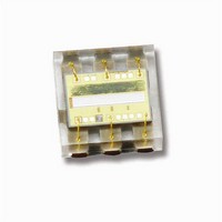
TSL2561T
Description
Light to Digital Converters Light to Digital with I2C
Manufacturer
TAOS
Specifications of TSL2561T
Maximum Operating Temperature
+ 70 C
Minimum Operating Temperature
- 30 C
Mounting Style
SMD/SMT
Package / Case
TMB
Response Time
400ms
Output Current
6mA
Supply Voltage Range Dc
2.7V To 3.6V
Supply Current
0.6mA
Operating Temperature Range
-30°C To +70°C
Operating Temperature Min
-30°C
Rohs Compliant
Yes
Operating Temperature Max
70°C
Sensor Output
I2C
Lead Free Status / RoHS Status
Lead free / RoHS Compliant
Available stocks
Company
Part Number
Manufacturer
Quantity
Price

Part Number:
TSL2561T
Manufacturer:
AMS
Quantity:
20 000


The LUMENOLOGY r Company
When an SMBus Block Write or Block Read is initiated (see description of COMMAND Register), the byte
following the COMMAND byte is ignored but is a requirement of the SMBus specification. This field contains
the byte count (i.e. the number of bytes to be transferred). The TSL2560 (SMBus) device ignores this field and
extracts this information by counting the actual number of bytes transferred before the Stop condition is
detected.
When an I
SMBus protocol specification. Data bytes continue to be transferred from the TSL2561 (I
until a NACK is sent by the Master.
The data formats supported by the TSL2560 and TSL2561 devices are:
D
D
D
For a complete description of SMBus protocols, please review the SMBus Specification at
http://www.smbus.org/specs. For a complete description of I
at http://www.semiconductors.philips.com.
Master transmitter transmits to slave receiver (SMBus and I
−
Master reads slave immediately after the first byte (SMBus only):
−
Combined format (SMBus and I
−
The transfer direction in this case is not changed.
At the moment of the first acknowledgment (provided by the slave receiver) the master transmitter
becomes a master receiver and the slave receiver becomes a slave transmitter.
During a change of direction within a transfer, the master repeats both a START condition and the slave
address but with the R/W bit reversed. In this case, the master receiver terminates the transfer by
generating a NACK on the last byte of the transfer and a STOP condition.
2
C Write or I
A
P
Rd
S
Sr
Wr
X
...
Figure 9. SMBus and I
2
C Read (Combined Format) is initiated, the byte count is also ignored but follows the
Acknowledge (this bit position may be 0 for an ACK or 1 for a NACK)
Stop Condition
Read (bit value of 1)
Start Condition
Repeated Start Condition
Write (bit value of 0)
Shown under a field indicates that that field is required to have a value of X
Continuation of protocol
Master-to-Slave
Slave-to-Master
1
S
Slave Address
r
7
2
C):
www.taosinc.com
Wr
2
1
C Packet Protocol Element Key
A
X
1
Data Byte
2
C protocols, please review the I
8
2
C):
LIGHT-TO-DIGITAL CONVERTER
r
1
A
X
1
P
TSL2560, TSL2561
Copyright E 2009, TAOS Inc.
2
C) device to Master
TAOS059N − MARCH 2009
2
C Specification
11
Related parts for TSL2561T
Image
Part Number
Description
Manufacturer
Datasheet
Request
R

Part Number:
Description:
Microcontroller Modules & Accessories TAOS Eval Module w/USB Interface
Manufacturer:
TAOS
Part Number:
Description:
Optical Sensor Development Tools TAOS Eval Module
Manufacturer:
TAOS

Part Number:
Description:
Industrial Optical Sensors Ambient Light Sensor SMBus
Manufacturer:
TAOS
Datasheet:

Part Number:
Description:
Photodiodes TriColor Sensor RGB, Clear Ch
Manufacturer:
TAOS
Datasheet:

Part Number:
Description:
LED Displays Hexadecimal Display 4-bit
Manufacturer:
TAOS
Datasheet:

Part Number:
Description:
Photodiodes Linear Sensor Array 200dpi 64pix
Manufacturer:
TAOS
Datasheet:

Part Number:
Description:
Industrial Optical Sensors Ambient Light Sensor SMBus
Manufacturer:
TAOS
Datasheet:

Part Number:
Description:
Photodiodes Linear Array 200 DPI
Manufacturer:
TAOS
Datasheet:

Part Number:
Description:
Photodiodes Light to Voltage Converter
Manufacturer:
TAOS
Datasheet:

Part Number:
Description:
Photodiodes Linear Array 200 DPI
Manufacturer:
TAOS
Datasheet:
Part Number:
Description:
Industrial Optical Sensors Ambient Light Sensor SMBus
Manufacturer:
TAOS
Datasheet:
Part Number:
Description:
Photodiodes TriColor Sensor RGB, Clear Ch
Manufacturer:
TAOS
Datasheet:
Part Number:
Description:
LED Displays Hexadecimal Display 4-bit
Manufacturer:
TAOS
Datasheet:
Part Number:
Description:
Photodiodes Linear Sensor Array 200dpi 64pix
Manufacturer:
TAOS
Datasheet:
