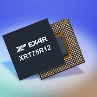
XRT75R12DIB-F Exar Corporation, XRT75R12DIB-F Datasheet - Page 35

XRT75R12DIB-F
Manufacturer Part Number
XRT75R12DIB-F
Description
Peripheral Drivers & Components (PCIs) 12 Channel 3.3V-5V temp -45 to 85C
Manufacturer
Exar Corporation
Datasheet
1.XRT75R12DIB-F.pdf
(133 pages)
Specifications of XRT75R12DIB-F
Maximum Operating Temperature
+ 85 C
Minimum Operating Temperature
- 40 C
Mounting Style
SMD/SMT
Operating Supply Voltage
3.3 V to 5 V
Package / Case
TBGA-420
Lead Free Status / RoHS Status
Lead free / RoHS Compliant
- Current page: 35 of 133
- Download datasheet (851Kb)
REV. 1.0.3
The XRT75R12D contains an on-chip Pseudo Random Binary Sequence (PRBS) generator and detector for
diagnostic purpose. With the PRBSEN_n bit = “1”, the transmitter will send out PRBS of 2
2
PRBS pattern is detected by the receiver, the RNEG/LCV pin will go “Low” to indicate PRBS synchronization
has been achieved. When the PRBS detector is not in sync the PRBSLS bit will be set to “1” and RNEG/LCV
pin will go “High”.
With the PRBS mode enabled, the user can also insert a single bit error by toggling “INSPRBS” bit. This is
done by writing a “1” to INSPRBS bit. The receiver at RNEG/LCV pin will pulse “High” for one RxClk cycle for
every bit error detected. Any subsequent single bit error insertion must be done by first writing a “0” to
INSPRBS bit and followed by a “1”.
Figure 17
N
F
5.0 DIAGNOSTIC FEATURES
5.1
15
OTE
IGURE
-1 in STS-1/DS3 rate. At the same time, the receiver PRBS detector is also enabled. When the correct
: In PRBS mode, the device is forced to operate in Single-Rail Mode.
17. PRBS MODE
PRBS Generator and Detector
shows the status of RNEG/LCV pin when the XRT75R12D is configured in PRBS mode.
TWELVE CHANNEL E3/DS3/STS-1 LINE INTERFACE UNIT WITH SONET DESYNCHRONIZER
RxNEG/LCV
RxClk
SYNC LOSS
PRBS SYNC
Single Bit Error
31
23
XRT75R12D
-1 in E3 rate or
Related parts for XRT75R12DIB-F
Image
Part Number
Description
Manufacturer
Datasheet
Request
R

Part Number:
Description:
Twelve Channel E3/ds3/sts-1 Line Interface Unit With Jitter
Manufacturer:
Exar Corporation
Datasheet:

Part Number:
Description:
BiCMOS Fixed, Quad, Voltage Output, Single or Dual Supply 8-Bit Digital-to-Analog Converter
Manufacturer:
Exar Corporation
Datasheet:

Part Number:
Description:
Manufacturer:
Exar Corporation
Datasheet:

Part Number:
Description:
Voltage-Controlled Oscillator
Manufacturer:
Exar Corporation
Datasheet:

Part Number:
Description:
INTEGRATED LINE TRANSMITTER
Manufacturer:
Exar Corporation
Datasheet:

Part Number:
Description:
Monolithic Function Generator
Manufacturer:
Exar Corporation
Datasheet:

Part Number:
Description:
CMOS Microprocessor Compatible Double-Buffered 12-Bit Digital-to-Analog Converter
Manufacturer:
Exar Corporation
Datasheet:

Part Number:
Description:
CMOS 6 BIT HIGH SPEED ANALOG TO DIGITAL CONVERTER
Manufacturer:
Exar Corporation
Datasheet:

Part Number:
Description:
Manufacturer:
Exar Corporation
Datasheet:

Part Number:
Description:
Manufacturer:
Exar Corporation
Datasheet:

Part Number:
Description:
8-Channel, Voltage Output 10 MHz Input Bandwidth 8-Bit Multiplying DACs with Serial Digital Data Por
Manufacturer:
Exar Corporation
Datasheet:

Part Number:
Description:
15 V CMOS Multiplying10-Bit Digital-to-Analog Converter
Manufacturer:
Exar Corporation
Datasheet:

Part Number:
Description:
Monolithic Function Generator
Manufacturer:
Exar Corporation
Datasheet:


