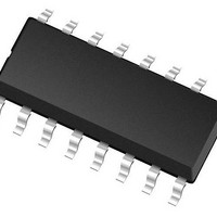
ALTAIR05T-800TR STMicroelectronics, ALTAIR05T-800TR Datasheet - Page 15

ALTAIR05T-800TR
Manufacturer Part Number
ALTAIR05T-800TR
Description
Switching Converters, Regulators & Controllers 800V Off-line QR Switching Regulator
Manufacturer
STMicroelectronics
Datasheet
1.ALTAIR05T-800TR.pdf
(28 pages)
Specifications of ALTAIR05T-800TR
Input Voltage
11.5 V to 23 V
Switching Frequency
166 KHz
Operating Temperature Range
- 55 C to + 150 C
Mounting Style
SMD/SMT
Package / Case
SOIC-16
Lead Free Status / RoHS Status
Lead free / RoHS Compliant
Available stocks
Company
Part Number
Manufacturer
Quantity
Price
Part Number:
ALTAIR05T-800TR
Manufacturer:
ST
Quantity:
20 000
ALTAIR05T-800
5.4
5.5
Constant voltage operation
The IC is specifically designed to work in primary regulation and the output voltage is
sensed through a voltage partition of the auxiliary winding, just before the auxiliary rectifier
diode.
Figure 13
connections.
Figure 13. Voltage control principle: internal schematic
Due to the parasitic wires resistance, the auxiliary voltage is representative of the output just
when the secondary current becomes zero. For this purpose, the signal on ZCD/FB pin is
sampled-and-held at the end of transformer’s demagnetization to get an accurate image of
the output voltage and it is compared with the error amplifier internal reference.
The COMP pin is used for the frequency compensation: usually, an RC network, which
stabilizes the overall voltage control loop, is connected between this pin and ground.
The output voltage can be defined according the formula:
Where N
The R
Voltage feedforward
Constant current operation
Figure 14
flyback converter.
ZCD
SEC
shows the internal schematic of the constant voltage mode and the external
presents the principle used for controlling the average output current of the
value can be defined depending on the application parameters (see
and N
AUX
Aux
block”).
Rzcd
R
are the secondary and auxiliary turn’s number respectively.
FB
=
R f b
-------------------------------------------------------- -
N
--------------
N
Doc ID 17957 Rev 1
AUX
SEC
⋅
D EMAG
V
V
LOGI C
S/ H
REF
OUT
–
2. 5V
V
REF
+
-
EA
COMP
⋅
R
ZCD
R
C
F rom Rsense
+
-
C V
To PWM Logic
Application information
“Section 5.6:
(1)
15/28


