B72540V300K62 EPCOS Inc, B72540V300K62 Datasheet - Page 65
B72540V300K62
Manufacturer Part Number
B72540V300K62
Description
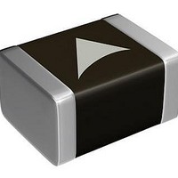
Varistors - MLV Varistor CN2220K30G
Manufacturer
EPCOS Inc
Specifications of B72540V300K62
Voltage Rating Dc
38 V
Voltage Rating Ac
30 V
Clamping Voltage
77 V
Peak Surge Current
1.2 KA
Capacitance
4000 pF
Operating Temperature Range
- 55 C to + 125 C
Mounting
SMD/SMT
Tolerance
10 %
Package / Case
2220
Suppressor Type
Varistor
Peak Surge Current @ 8/20µs
1.2kA
Varistor Case
2220
Peak Energy (10/1000us)
12J
Voltage Rating Vdc
38V
Voltage Rating Vac
30Vrms
Rohs Compliant
Yes
Technology
Multilayer Single
Capacitance Value
4000pF
Clamping Current
10A
Energy
12Joule
Ac Voltage Rating (max)
30VAC
Dc Voltage Rating (max)
38VDC
Operating Temp Range
-55C to 125C
Surge Current (max)
1200A
Size Code
2220
Varistor Voltage
47V
Product Length (mm)
5.7mm
Product Depth (mm)
5mm
Product Height (mm)
2.5mm
Product Diameter (mm)
Not Requiredmm
Lead Free Status / RoHS Status
Lead free / RoHS Compliant
Other names
B72540V0300K062
Available stocks
Company
Part Number
Manufacturer
Quantity
Price
Company:

Part Number:
B72540V300K62
Manufacturer:
HRS
Quantity:
5 000


7.5
Thin or insufficient adhesive causes chips to loosen or become disconnected during curing.
Low viscosity of the adhesive causes chips to slip after mounting. It is advised to consult the
manufacturer of the adhesive on proper usage and amounts of adhesive to use.
7.6
Used flux should have less than or equal to 0.1 wt % of halogenated content, since flux residue
after soldering could lead to corrosion of the termination and/or increased leakage current on the
surface of the component. Strong acidic flux must not be used. The amount of flux applied should
be carefully controlled, since an excess may generate flux gas, which in turn is detrimental to sol-
derability.
7.7
Solderability is guaranteed for one year from date of delivery for multilayer varistors, CeraDiodes
and ESD/EMI filters (half a year for chips with AgPd and AgPt terminations) and two years for
SHCV and CU components, provided that components are stored in their original packages.
Storage temperature:
Relative humidity:
The solderability of the external electrodes may deteriorate if SMDs and leaded components are
stored where they are exposed to high humidity, dust or harmful gas (hydrogen chloride, sulfurous
acid gas or hydrogen sulfide).
Do not store SMDs and leaded components where they are exposed to heat or direct sunlight.
Otherwise the packing material may be deformed or SMDs/ leaded components may stick togeth-
er, causing problems during mounting.
After opening the factory seals, such as polyvinyl-sealed packages, it is recommended to use the
SMDs or leaded components as soon as possible.
7.8
Especially in the case of dual-wave soldering, it is of advantage to place the components on the
board before soldering in that way that their two terminals do not enter the solder bath at different
times.
Ideally, both terminals should be wetted simultaneously.
7.9
Please read Cautions and warnings and
Important notes at the end of this document.
Multilayer varistors (MLVs)
Automotive series
An excessively long soldering time or high soldering temperature results in leaching of the outer
electrodes, causing poor adhesion and a change of electrical properties of the varistor due to
the loss of contact between electrodes and termination.
Wave soldering must not be applied for MLVs designated for reflow soldering only.
Keep the recommended down-cooling rate.
Adhesive application
Selection of flux
Storage of CTVSs
Placement of components on circuit board
Soldering cautions
75% annual average, 95% on 30 days a year
25 C to +45 C
Page 65 of 72
Related parts for B72540V300K62
Image
Part Number
Description
Manufacturer
Datasheet
Request
R

Part Number:
Description:
VARISTOR 25VRMS 2220 SMD
Manufacturer:
EPCOS Inc
Datasheet:
Part Number:
Description:
VARISTOR 35VRMS 2220 SMD
Manufacturer:
EPCOS Inc
Datasheet:
Part Number:
Description:
VARISTOR 40VRMS 2220 SMD
Manufacturer:
EPCOS Inc
Datasheet:
Part Number:
Description:
VARISTOR 50VRMS 2220 SMD
Manufacturer:
EPCOS Inc
Datasheet:
Part Number:
Description:
VARISTOR 8VRMS 2220 SMD
Manufacturer:
EPCOS Inc
Datasheet:
Part Number:
Description:
VARISTOR 11VRMS 2220 SMD
Manufacturer:
EPCOS Inc
Datasheet:
Part Number:
Description:
VARISTOR 14VRMS 2220 SMD
Manufacturer:
EPCOS Inc
Datasheet:
Part Number:
Description:
VARISTOR 17VRMS 2220 SMD
Manufacturer:
EPCOS Inc
Datasheet:
Part Number:
Description:
VARISTOR 20VRMS 2220 SMD
Manufacturer:
EPCOS Inc
Datasheet:

