B72540V300K62 EPCOS Inc, B72540V300K62 Datasheet - Page 70
B72540V300K62
Manufacturer Part Number
B72540V300K62
Description
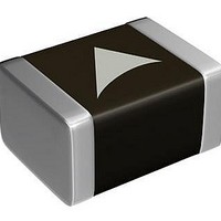
Varistors - MLV Varistor CN2220K30G
Manufacturer
EPCOS Inc
Specifications of B72540V300K62
Voltage Rating Dc
38 V
Voltage Rating Ac
30 V
Clamping Voltage
77 V
Peak Surge Current
1.2 KA
Capacitance
4000 pF
Operating Temperature Range
- 55 C to + 125 C
Mounting
SMD/SMT
Tolerance
10 %
Package / Case
2220
Suppressor Type
Varistor
Peak Surge Current @ 8/20µs
1.2kA
Varistor Case
2220
Peak Energy (10/1000us)
12J
Voltage Rating Vdc
38V
Voltage Rating Vac
30Vrms
Rohs Compliant
Yes
Technology
Multilayer Single
Capacitance Value
4000pF
Clamping Current
10A
Energy
12Joule
Ac Voltage Rating (max)
30VAC
Dc Voltage Rating (max)
38VDC
Operating Temp Range
-55C to 125C
Surge Current (max)
1200A
Size Code
2220
Varistor Voltage
47V
Product Length (mm)
5.7mm
Product Depth (mm)
5mm
Product Height (mm)
2.5mm
Product Diameter (mm)
Not Requiredmm
Lead Free Status / RoHS Status
Lead free / RoHS Compliant
Other names
B72540V0300K062
Available stocks
Company
Part Number
Manufacturer
Quantity
Price
Company:

Part Number:
B72540V300K62
Manufacturer:
HRS
Quantity:
5 000


Storage
Handling
Mounting
Soldering
Please read Cautions and warnings and
Important notes at the end of this document.
Multilayer varistors (MLVs)
Automotive series
Specified values only apply to CTVS components that have not been subject to prior electrical,
mechanical or thermal damage. The use of CTVS devices in line-to-ground applications is
therefore not advisable, and it is only allowed together with safety countermeasures like
thermal fuses.
Only store CTVS in their original packaging. Do not open the package before storage.
Storage conditions in original packaging: temperature
annual average, maximum 95%, dew precipitation is inadmissible.
Do not store CTVS devices where they are exposed to heat or direct sunlight. Otherwise the
packaging material may be deformed or CTVS may stick together, causing problems during
mounting.
Avoid contamination of the CTVS surface during storage, handling and processing.
Avoid storing CTVS devices in harmful environments where they are exposed to corrosive
gases for example (SO
Use CTVS as soon as possible after opening factory seals such as polyvinyl-sealed packages.
Solder CTVS components after shipment from EPCOS within the time specified:
Do not drop CTVS components and allow them to be chipped.
Do not touch CTVS with your bare hands - gloves are recommended.
Avoid contamination of the CTVS surface during handling.
When CTVS devices are encapsulated with sealing material or overmolded with plastic
material, electrical characteristics might be degraded and the life time reduced.
Make sure an electrode is not scratched before, during or after the mounting process.
Make sure contacts and housings used for assembly with CTVS components are clean before
mounting.
The surface temperature of an operating CTVS can be higher. Ensure that adjacent
components are placed at a sufficient distance from a CTVS to allow proper cooling.
Avoid contamination of the CTVS surface during processing.
Multilayer varistors (MLVs) with AgPd termination are not approved for lead-free soldering.
Complete removal of flux is recommended to avoid surface contamination that can result in an
instable and/or high leakage current.
Use resin-type or non-activated flux.
Bear in mind that insufficient preheating may cause ceramic cracks.
Rapid cooling by dipping in solvent is not recommended, otherwise a component may crack.
CTVS with Ni barrier termination, 12 months
CTVS with AgPd and AgPt termination, 6 months
SHCV and CU series, 24 months
x
, Cl).
Page 70 of 72
25 to +45 C, relative humidity 75%
Related parts for B72540V300K62
Image
Part Number
Description
Manufacturer
Datasheet
Request
R

Part Number:
Description:
VARISTOR 25VRMS 2220 SMD
Manufacturer:
EPCOS Inc
Datasheet:
Part Number:
Description:
VARISTOR 35VRMS 2220 SMD
Manufacturer:
EPCOS Inc
Datasheet:
Part Number:
Description:
VARISTOR 40VRMS 2220 SMD
Manufacturer:
EPCOS Inc
Datasheet:
Part Number:
Description:
VARISTOR 50VRMS 2220 SMD
Manufacturer:
EPCOS Inc
Datasheet:
Part Number:
Description:
VARISTOR 8VRMS 2220 SMD
Manufacturer:
EPCOS Inc
Datasheet:
Part Number:
Description:
VARISTOR 11VRMS 2220 SMD
Manufacturer:
EPCOS Inc
Datasheet:
Part Number:
Description:
VARISTOR 14VRMS 2220 SMD
Manufacturer:
EPCOS Inc
Datasheet:
Part Number:
Description:
VARISTOR 17VRMS 2220 SMD
Manufacturer:
EPCOS Inc
Datasheet:
Part Number:
Description:
VARISTOR 20VRMS 2220 SMD
Manufacturer:
EPCOS Inc
Datasheet:

