PVG3A103C01R00 Murata, PVG3A103C01R00 Datasheet - Page 51
PVG3A103C01R00
Manufacturer Part Number
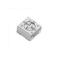
PVG3A103C01R00
Description
Trimmer Resistors - SMD 10Kohms Sealed 3mm Single turn
Manufacturer
Murata
Series
PVG3Ar
Type
Trimmerr
Datasheet
1.PVG3A103C01R00.pdf
(59 pages)
Specifications of PVG3A103C01R00
Resistance
10 KOhms
Power Rating
0.25 Watt (1/4 Watt)
Operating Temperature Range
- 55 C to + 125 C
Element Type
Cermet
Dimensions
3.4 mm W x 3.6 mm L x 2 mm H
Product
Single-Turn Trimmer Potentiometers
Termination Style
SMD/SMT
Tolerance
20 %
Number Of Turns
1
Taper
Linear
Temperature Coefficient
+/- 150 PPM / C
Tolerance (+ Or -)
20%
Technology
Cermet
Mounting Style
Surface Mount
Operating Temp Range
-55C to 125C
Failure Rate
Not Required
Shaft Diameter (mm)
2.2mm
Product Diameter (mm)
Not Requiredmm
Product Length (mm)
3.6mm
Product Height (mm)
2mm
Product Depth (mm)
3.6mm
Lead Free Status / RoHS Status
Lead free / RoHS Compliant
Available stocks
Company
Part Number
Manufacturer
Quantity
Price
Company:

Part Number:
PVG3A103C01R00
Manufacturer:
MURATA
Quantity:
240 000


!Note
• This PDF catalog is downloaded from the website of Murata Manufacturing co., ltd. Therefore, it’s specifications are subject to change or our products in it may be discontinued without advance notice. Please check with our
• This PDF catalog has only typical specifications because there is no space for detailed specifications. Therefore, please approve our product specifications or transact the approval sheet for product specifications before ordering.
sales representatives or product engineers before ordering.
!Note
1
No.
The following describes trimmer potentiometer testing conducted by Murata Manufacturing Co., Ltd. in accordance with MIL-R-22097 (Military specification
for variable resistors, non-wirewound) and MIL-STD-202 (Test methods for electronic and electrical component parts).
1
2
3
4
5
Specifications and Test Methods
SMD Sealed Type (PVF2/G3/M4A_D01/G5)/Lead Sealed Type (PV32/12/37/36) Specifications and Test Methods
Total Resistance
Residual Resistance
Contact Resistance
Variation
Temperature Coefficient of
Resistance
Voltage Setting
Stability
• Please read rating and !CAUTION (for storage, operating, rating, soldering, mounting and handling) in this catalog to prevent smoking and/or burning, etc.
• This catalog has only typical specifications because there is no space for detailed specifications. Therefore, please approve our product specifications or transact the approval sheet for product specifications before ordering.
Item
Measure total resistance between the resistance element and terminals (#1 and #3) with the contact arm positioned
against a stop. The positioning of the contact arm and terminal should be the same for subsequent total resistance
measurements on the same device. Use the test voltage specified in Table 1 for total resistance measurements.
This voltage should be used for all subsequent total resistance measurements.
Position the contact arm at the extreme counterclockwise limit of mechanical travel and measure the resistance
between the contact arm and the corresponding end terminal. Then, position the contact arm at the extreme clock-
wise limit of mechanical travel and measure the resistance between the contact arm and the corresponding end ter-
minal. During this test, take suitable precautions to ensure that the rated current of the resistance element is not
exceeded.
Contact resistance variation should be measured with the measuring circuit shown in Figure 1, or its equivalent. The
adjustment rotor (screw) should be rotated in both directions through 90% of the actual effective-electrical rotational
angle (number of turns) for a total of 6 cycles. Only the last 3 cycles should count in determining whether or not a
contact resistance variation is observed at least twice in the same location, exclusive of the roll-on or roll-off points
where the contact arm moves from the termination, on or off, the resistance element. The rate of rotation of the
adjustment rotor (screw) should be such that the adjustment rotor (screw) completes 1 cycle for 5 seconds minimum
to 2 minutes maximum. The test current used should follow the value given in Table 2 unless otherwise limited by
power rating.
The trimmer potentiometer should be subjected to each of the following temperatures (see Table 3) for 30-45 min-
utes. Temperature coefficient of resistance should be applied to the following formula.
TCR=
Note*: Reference temperature
The wiper should be set at approximately 40% of the actual effective-electrical rotational angle (number of turns). An
adequate DC test potential should be applied between terminal #1 and terminal #3. The voltage between terminal #1
and terminal #3, and the voltage between terminal #1 and terminal #2, should be measured and applied to the
following formula.
Voltage setting stability=
e : Before test
e': After test
Standard Total Resistance
Total Resistance,
Temperature (°C)
(The voltage between terminal #1 and terminal #2)
(The voltage between terminal #1 and terminal #2)
100kFR
Nominal (ohm)
Table 1: Total resistance test voltage
100FRV1k
10kFRV100k
10VRV100
Sequence
1kFRV10k
200kVRF1M
R
T
T
R
R
100FRF500
500VRF1k
50kVRF200k
1MVRF2M
2MVR
Table 2: Test current for CRV
1
R
1
2
1kVRF2k
2kVRF50k
1
2
(T
R (ohm)
2
: Reference temperature in degrees celsius
: Test temperature in degrees celsius
: Resistance at reference temperature ohm
: Resistance at test temperature in ohm
– R
2
RV100
– T
1
1
)
Z 10
+25
(
Maximum Test
1*
6
e'
E
Voltage (V)
(ppm/°C)
–
100.0
10.0
30.0
E
e
1.0
3.0
Table 3: Test temperatures
Test Current
)
-15
2
Z100 (%)
200µA
100µA
20mA
10mA
50µA
30µA
4mA
2mA
1mA
Min. operating
Temperature
3
Test Methods
Constant Current Source
(Test current shown in Table 2)
+25
4*
#1
+65
Rx : Trimmer Potentiometer
Oscilloscope bandwidth :100Hz to 50kHz
5
Figure 1: CRV measuring circuit
Max. operating
Temperature
#1
e
Resistance
Proofread
#2
Rx
6
Figure 2
Continued on the following page.
E
#3
#2
AC
Amplifier
#3
Oscilloscope
R50E.pdf
49
08.8.26
8
Related parts for PVG3A103C01R00
Image
Part Number
Description
Manufacturer
Datasheet
Request
R

Part Number:
Description:
Murata Microblower 20x20 DCDC Driver Board - Samples Only
Manufacturer:
Murata
Part Number:
Description:
357-036-542-201 CARDEDGE 36POS DL .156 BLK LOPRO
Manufacturer:
Murata
Datasheet:
Part Number:
Description:
Manufacturer:
Murata
Datasheet:
Part Number:
Description:
Manufacturer:
Murata
Datasheet:
Part Number:
Description:
Manufacturer:
Murata
Datasheet:
Part Number:
Description:
Manufacturer:
Murata
Datasheet:
Part Number:
Description:
Manufacturer:
Murata
Datasheet:
Part Number:
Description:
Manufacturer:
Murata
Datasheet:
Part Number:
Description:
Manufacturer:
Murata
Datasheet:
Part Number:
Description:
BLM21BD751SN1On-Board Type (DC) EMI Suppression Filters
Manufacturer:
Murata
Datasheet:
Part Number:
Description:
BLM15AG100SN1On-Board Type (DC) EMI Suppression Filters
Manufacturer:
Murata
Datasheet:
Part Number:
Description:
NFE31PT222Z1E9On-Board Type (DC) EMI Suppression Filters
Manufacturer:
Murata
Datasheet:
Part Number:
Description:
Chip Coil
Manufacturer:
Murata
Datasheet:
Part Number:
Description:
Chip Coil
Manufacturer:
Murata
Datasheet: