DS1822+ Maxim Integrated Products, DS1822+ Datasheet - Page 10
DS1822+
Manufacturer Part Number
DS1822+
Description
Board Mount Temperature Sensors IC THERMOMETER ECONO DIG
Manufacturer
Maxim Integrated Products
Datasheet
1.DS1822Z.pdf
(21 pages)
Specifications of DS1822+
Temperature Threshold
Programmable
Full Temp Accuracy
+/- 2 C
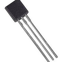
Package / Case
TO-92
Digital Output - Bus Interface
1-Wire
Digital Output - Number Of Bits
9 bit to 12 bit
Supply Voltage (max)
5.5 V
Supply Voltage (min)
3 V
Maximum Operating Temperature
+ 125 C
Minimum Operating Temperature
- 55 C
Output Type
Digital
Supply Current
1.5 mA
Ic Output Type
Digital
Sensing Accuracy Range
± 2°C
Supply Voltage Range
3V To 5.5V
Resolution (bits)
12bit
Sensor Case Style
TO-92
No. Of Pins
3
Accuracy %
2°C
Rohs Compliant
Yes
Lead Free Status / RoHS Status
Lead free / RoHS Compliant


DS1822
TRANSACTION SEQUENCE
The transaction sequence for accessing the DS1822 is as follows:
Step 1. Initialization
Step 2. ROM Command (followed by any required data exchange)
Step 3. DS1822 Function Command (followed by any required data exchange)
It is very important to follow this sequence every time the DS1822 is accessed, as the DS1822 will not
respond if any steps in the sequence are missing or out of order. Exceptions to this rule are the Search
ROM [F0h] and Alarm Search [ECh] commands. After issuing either of these ROM commands, the
master must return to Step 1 in the sequence.
INITIALIZATION
All transactions on the 1-Wire bus begin with an initialization sequence. The initialization sequence
consists of a reset pulse transmitted by the bus master followed by presence pulse(s) transmitted by the
slave(s). The presence pulse lets the bus master know that slave devices (such as the DS1822) are on the
bus and are ready to operate. Timing for the reset and presence pulses is detailed in the
1-WIRE SIGNALING section.
ROM COMMANDS
After the bus master has detected a presence pulse, it can issue a ROM command. These commands
operate on the unique 64–bit ROM codes of each slave device and allow the master to single out a
specific device if many are present on the 1-Wire bus. These commands also allow the master to
determine how many and what types of devices are present on the bus or if any device has experienced an
alarm condition. There are five ROM commands, and each command is 8 bits long. The master device
must issue an appropriate ROM command before issuing a DS1822 function command. A flowchart for
operation of the ROM commands is shown in Figure 11.
SEARCH ROM [F0h]
When a system is initially powered up, the master must identify the ROM codes of all slave devices on
the bus, which allows the master to determine the number of slaves and their device types. The master
learns the ROM codes through a process of elimination that requires the master to perform a Search ROM
cycle (i.e., Search ROM command followed by data exchange) as many times as necessary to identify all
of the slave devices. If there is only one slave on the bus, the simpler Read ROM command (see below)
can be used in place of the Search ROM process. For a detailed explanation of the Search ROM
procedure, refer to the iButton Book of Standards at www.ibutton.com/ibuttons/standard.pdf. After every
Search ROM cycle, the bus master must return to Step 1 (Initialization) in the transaction sequence.
READ ROM [33h]
This command can only be used when there is one slave on the bus. It allows the bus master to read the
slave’s 64-bit ROM code without using the Search ROM procedure. If this command is used when there
is more than one slave present on the bus, a data collision will occur when all the slaves attempt to
respond at the same time.
MATCH ROM [55h]
The match ROM command followed by a 64-bit ROM code sequence allows the bus master to address a
specific slave device on a multidrop or single-drop bus. Only the slave that exactly matches the 64-bit
ROM code sequence will respond to the function command issued by the master; all other slaves on the
bus will wait for a reset pulse.
10 of 21
Related parts for DS1822+
Image
Part Number
Description
Manufacturer
Datasheet
Request
R

Part Number:
Description:
MAX7528KCWPMaxim Integrated Products [CMOS Dual 8-Bit Buffered Multiplying DACs]
Manufacturer:
Maxim Integrated Products
Datasheet:
Part Number:
Description:
Single +5V, fully integrated, 1.25Gbps laser diode driver.
Manufacturer:
Maxim Integrated Products
Datasheet:
Part Number:
Description:
Single +5V, fully integrated, 155Mbps laser diode driver.
Manufacturer:
Maxim Integrated Products
Datasheet:
Part Number:
Description:
VRD11/VRD10, K8 Rev F 2/3/4-Phase PWM Controllers with Integrated Dual MOSFET Drivers
Manufacturer:
Maxim Integrated Products
Datasheet:
Part Number:
Description:
Highly Integrated Level 2 SMBus Battery Chargers
Manufacturer:
Maxim Integrated Products
Datasheet:
Part Number:
Description:
Current Monitor and Accumulator with Integrated Sense Resistor; ; Temperature Range: -40°C to +85°C
Manufacturer:
Maxim Integrated Products
Part Number:
Description:
TSSOP 14/A�/RS-485 Transceivers with Integrated 100O/120O Termination Resis
Manufacturer:
Maxim Integrated Products
Part Number:
Description:
TSSOP 14/A�/RS-485 Transceivers with Integrated 100O/120O Termination Resis
Manufacturer:
Maxim Integrated Products
Part Number:
Description:
QFN 16/A�/AC-DC and DC-DC Peak-Current-Mode Converters with Integrated Step
Manufacturer:
Maxim Integrated Products
Part Number:
Description:
TDFN/A/65V, 1A, 600KHZ, SYNCHRONOUS STEP-DOWN REGULATOR WITH INTEGRATED SWI
Manufacturer:
Maxim Integrated Products
Part Number:
Description:
Integrated Temperature Controller f
Manufacturer:
Maxim Integrated Products
Part Number:
Description:
SOT23-6/I�/45MHz to 650MHz, Integrated IF VCOs with Differential Output
Manufacturer:
Maxim Integrated Products
Part Number:
Description:
SOT23-6/I�/45MHz to 650MHz, Integrated IF VCOs with Differential Output
Manufacturer:
Maxim Integrated Products
Part Number:
Description:
EVALUATION KIT/2.4GHZ TO 2.5GHZ 802.11G/B RF TRANSCEIVER WITH INTEGRATED PA
Manufacturer:
Maxim Integrated Products
Part Number:
Description:
QFN/E/DUAL PCIE/SATA HIGH SPEED SWITCH WITH INTEGRATED BIAS RESISTOR
Manufacturer:
Maxim Integrated Products
Datasheet: