DS1822+ Maxim Integrated Products, DS1822+ Datasheet - Page 6
DS1822+
Manufacturer Part Number
DS1822+
Description
Board Mount Temperature Sensors IC THERMOMETER ECONO DIG
Manufacturer
Maxim Integrated Products
Datasheet
1.DS1822Z.pdf
(21 pages)
Specifications of DS1822+
Temperature Threshold
Programmable
Full Temp Accuracy
+/- 2 C
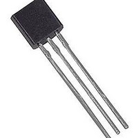
Package / Case
TO-92
Digital Output - Bus Interface
1-Wire
Digital Output - Number Of Bits
9 bit to 12 bit
Supply Voltage (max)
5.5 V
Supply Voltage (min)
3 V
Maximum Operating Temperature
+ 125 C
Minimum Operating Temperature
- 55 C
Output Type
Digital
Supply Current
1.5 mA
Ic Output Type
Digital
Sensing Accuracy Range
± 2°C
Supply Voltage Range
3V To 5.5V
Resolution (bits)
12bit
Sensor Case Style
TO-92
No. Of Pins
3
Accuracy %
2°C
Rohs Compliant
Yes
Lead Free Status / RoHS Status
Lead free / RoHS Compliant


The use of parasite power is not recommended for temperatures above 100°C since the DS1822 may not
be able to sustain communications due to the higher leakage currents that can exist at these temperatures.
For applications in which such temperatures are likely, it is strongly recommended that the DS1822 be
powered by an external power supply.
In some situations the bus master may not know whether the DS1822s on the bus are parasite powered or
powered by external supplies. The master needs this information to determine if the strong bus pullup
should be used during temperature conversions. To get this information, the master can issue a Skip ROM
[CCh] command followed by a Read Power Supply [B4h] command followed by a “read-time slot”.
During the read time slot, parasite powered DS1822s will pull the bus low, and externally powered
DS1822s will let the bus remain high. If the bus is pulled low, the master knows that it must supply the
strong pullup on the 1-Wire bus during temperature conversions.
SUPPLYING THE PARASITE-POWERED DS1822 DURING TEMPERATURE
CONVERSIONS Figure 4
POWERING THE DS1822 WITH AN EXTERNAL SUPPLY Figure 5
64-BIT LASERED ROM CODE
Each DS1822 contains a unique 64–bit code (see Figure 6) stored in ROM. The least significant 8 bits of
the ROM code contain the DS1822’s 1-Wire family code: 22h. The next 48 bits contain a unique serial
number. The most significant 8 bits contain a cyclic redundancy check (CRC) byte that is calculated from
the first 56 bits of the ROM code. A detailed explanation of the CRC bits is provided in the CRC
GENERATION section. The 64-bit ROM code and associated ROM function control logic allow the
DS1822 to operate as a 1-Wire device using the protocol detailed in the 1-WIRE BUS SYSTEM section
of this data sheet.
64-BIT LASERED ROM CODE Figure 6
MSB
8-BIT CRC
processor
Micro-
processor
Micro-
LSB
V
PU
V
MSB
PU
4.7k
4.7k
48-BIT SERIAL NUMBER
1-Wire Bus
6 of 21
V
PU
1-Wire Bus
GND
DS1822
DQ
LSB
V
DD
GND
DS1822
MSB
8-BIT FAMILY CODE (22h)
DQ
V
DD
V
(External Supply)
DD
To Other
1-Wire Devices
To Other
1-Wire Devices
DS1822
LSB
Related parts for DS1822+
Image
Part Number
Description
Manufacturer
Datasheet
Request
R

Part Number:
Description:
MAX7528KCWPMaxim Integrated Products [CMOS Dual 8-Bit Buffered Multiplying DACs]
Manufacturer:
Maxim Integrated Products
Datasheet:
Part Number:
Description:
Single +5V, fully integrated, 1.25Gbps laser diode driver.
Manufacturer:
Maxim Integrated Products
Datasheet:
Part Number:
Description:
Single +5V, fully integrated, 155Mbps laser diode driver.
Manufacturer:
Maxim Integrated Products
Datasheet:
Part Number:
Description:
VRD11/VRD10, K8 Rev F 2/3/4-Phase PWM Controllers with Integrated Dual MOSFET Drivers
Manufacturer:
Maxim Integrated Products
Datasheet:
Part Number:
Description:
Highly Integrated Level 2 SMBus Battery Chargers
Manufacturer:
Maxim Integrated Products
Datasheet:
Part Number:
Description:
Current Monitor and Accumulator with Integrated Sense Resistor; ; Temperature Range: -40°C to +85°C
Manufacturer:
Maxim Integrated Products
Part Number:
Description:
TSSOP 14/A�/RS-485 Transceivers with Integrated 100O/120O Termination Resis
Manufacturer:
Maxim Integrated Products
Part Number:
Description:
TSSOP 14/A�/RS-485 Transceivers with Integrated 100O/120O Termination Resis
Manufacturer:
Maxim Integrated Products
Part Number:
Description:
QFN 16/A�/AC-DC and DC-DC Peak-Current-Mode Converters with Integrated Step
Manufacturer:
Maxim Integrated Products
Part Number:
Description:
TDFN/A/65V, 1A, 600KHZ, SYNCHRONOUS STEP-DOWN REGULATOR WITH INTEGRATED SWI
Manufacturer:
Maxim Integrated Products
Part Number:
Description:
Integrated Temperature Controller f
Manufacturer:
Maxim Integrated Products
Part Number:
Description:
SOT23-6/I�/45MHz to 650MHz, Integrated IF VCOs with Differential Output
Manufacturer:
Maxim Integrated Products
Part Number:
Description:
SOT23-6/I�/45MHz to 650MHz, Integrated IF VCOs with Differential Output
Manufacturer:
Maxim Integrated Products
Part Number:
Description:
EVALUATION KIT/2.4GHZ TO 2.5GHZ 802.11G/B RF TRANSCEIVER WITH INTEGRATED PA
Manufacturer:
Maxim Integrated Products
Part Number:
Description:
QFN/E/DUAL PCIE/SATA HIGH SPEED SWITCH WITH INTEGRATED BIAS RESISTOR
Manufacturer:
Maxim Integrated Products
Datasheet: