H5CX-AD-N AC24/DC12-24 Omron, H5CX-AD-N AC24/DC12-24 Datasheet - Page 3
H5CX-AD-N AC24/DC12-24
Manufacturer Part Number
H5CX-AD-N AC24/DC12-24
Description
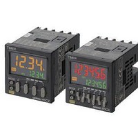
Stopwatches / Timers SCREW TERM RLY OUT Multi-Function
Manufacturer
Omron
Series
H5CXr
Datasheet
1.Y92P-CXT4B.pdf
(44 pages)
Specifications of H5CX-AD-N AC24/DC12-24
Timing Range
0.001 s to 9999 Hrs
Supply Voltage
12 V to 24 V
Current Rating (max)
100 mA
Display Type
4 Digit LCD Backlight
Product
Digital Timer
Termination Style
Screw
Time Range
0.001s-9999hrs
Power Consumption
2.4W
Reset Time
20ms
Character Size
11.5mm
Mounting Type
Panel
Time Range Min
0.001s
Supply Voltage Min
12V
Connector Type
Screw Terminal
Relay Type
Integrated
Function
Programmable (Multi-Function)
Circuit
SPDT (1 Form C)
Delay Time
0.001 Sec ~ 9999 Hrs
Output Type
Mechanical Relay
Contact Rating @ Voltage
5A @ 250VAC
Voltage - Supply
12 ~ 24VDC, 24VAC
Timing Adjustment Method
DIP Switches
Timing Initiate Method
Input Voltage, Trigger Signal
No. Of Digits / Alpha
4
Rohs Compliant
Yes
Lead Free Status / RoHS Status
Lead free / RoHS Compliant
For Use With
PNP/NPN
Lead Free Status / RoHS Status
Lead free / RoHS Compliant, Lead free / RoHS Compliant


Model Number Legend
H5CX- @@@@@-N
1. Type Classifier
4. Output type
* Can be used as a time-limit DPDT output.
Ordering Information
List of Models
Note: 1. The functions that are provided depend on the model. Check detailed specifications before ordering.
H5CX-A
H5CX-L
H5CX-B
Symbol
Symbol
None
Type
A
B
E
S
L
2. Refer to page 33 and later for information on H5CX-B Timers (6-digit display).
– – – – –
1 2 3 4 5
0.001 to 9.999 s
0.01 to 99.99 s
0.1 to 999.9 s
1 to 9999 s
1 s to 99 min 59 s
0.1 to 999.9 min
1 to 9999 min
1 min to 99 h 59 min
0.1 to 999.9 h
1 to 9999 h
0.01 to 9999.99 s
1 s to 99 h 59 min 59 s
0.1 to 99999.9 min
0.1 to 99999.9 h
Contact output (time-limit SPDT)
SPDT + instantaneous SPDT)
Time specifications
Contact output (time-limit
Transistor output
Standard type
Economy type
6-digit type
Meaning
Meaning
Timer Mode
Twin Timer Mode
Timer Mode
Twin Timer Mode
A: Signal ON Delay I
F-1: Cumulative
A: Signal ON Delay I
A-1: Signal ON Delay II
A-2: Power ON Delay I
A-3: Power ON Delay II
b: Repeat cycle 1
b-1: Repeat cycle 2
d: Signal OFF Delay
E: Interval
F: Cumulative
Z: ON/OFF-duty-adjustable flicker
S: Stopwatch
toff: Flicker OFF Start 1
ton: Flicker ON Start 1
toff-1: Flicker OFF Start 2
ton-1: Flicker ON Start 2
A-2: Power ON Delay I
b: Repeat cycle 1
E: Interval
Z: ON/OFF-duty-adjustable flicker
toff: Flicker OFF Start 1
ton: Flicker ON Start 1
(Not all possible combinations of functions are available.)
Operating modes
*
2. External Connections
5. Supply voltage
* The H5CX-BWSD-N is available only for 12 to 24 VDC.
Symbol
Symbol
None
None
11
D
8
12 to 24 VDC/24 VAC 50/60 Hz
Screw terminals
11-pin socket
8-pin socket
Screw terminals
connections
100 to 240 VAC 50/60 Hz
External
Screw terminals
11-pin socket
8-pin socket
Meaning
Meaning
Signal, Reset,
Gate (NPN/
PNP inputs)
Signal, Reset
(NPN inputs)
None
Signal, Reset,
Gate (NPN/
PNP inputs)
Inputs
*
Contact output
(time-limit
SPDT)
Transistor
output (SPST)
Contact output
(time-limit
SPDT)
Transistor
output (SPST)
Contact output
(time-limit
SPDT)
Transistor
output (SPST)
Contact output
(time-limit SPDT
+ instantaneous
SPDT)
Models with
instantaneous
contact outputs
Transistor
output (DPST)
Outputs
3. Settings
Symbol
None
W
100 to 240 VAC
12 to 24 VDC/
24 VAC
100 to 240 VAC
12 to 24 VDC/
24 VAC
100 to 240 VAC
12 to 24 VDC/
24 VAC
100 to 240 VAC
12 to 24 VDC/
24 VAC
100 to 240 VAC
12 to 24 VDC/
24 VAC
100 to 240 VAC
12 to 24 VDC/
24 VAC
100 to 240 VAC
12 to 24 VDC/
24 VAC
12 to 24 VDC
Supply voltage
Two stages
One stage
Meaning
H5CX-@-N
H5CX-A-N
H5CX-AD-N
H5CX-AS-N
H5CX-ASD-N
H5CX-A11-N
H5CX-A11D-N
H5CX-A11S-N
H5CX-A11SD-N
H5CX-L8-N
H5CX-L8D-N
H5CX-L8S-N
H5CX-L8SD-N
H5CX-L8E-N
H5CX-L8ED-N
H5CX-BWSD-N
Models
3