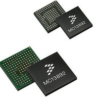
MC13892VK Freescale Semiconductor, MC13892VK Datasheet - Page 54

MC13892VK
Manufacturer Part Number
MC13892VK
Description
IC PMU I.MX51/37/35/27 139MAPBGA
Manufacturer
Freescale Semiconductor
Datasheets
1.MC13892AJVLR2.pdf
(156 pages)
2.MC13892AJVLR2.pdf
(2 pages)
3.MC13892AJVLR2.pdf
(16 pages)
Specifications of MC13892VK
Applications
Battery Management, Display (LED Drivers), Handheld/Mobile Devices, Power Supply
Operating Temperature
-40°C ~ 85°C
Mounting Type
Surface Mount
Package / Case
*
Output Current
65 mA
Output Voltage
1.5 V
Lead Free Status / RoHS Status
Lead free / RoHS Compliant
Current - Supply
-
Voltage - Supply
-
Lead Free Status / Rohs Status
Lead free / RoHS Compliant
Available stocks
Company
Part Number
Manufacturer
Quantity
Price
Company:
Part Number:
MC13892VK
Manufacturer:
FREESCALE
Quantity:
2 248
Company:
Part Number:
MC13892VK
Manufacturer:
Freescale Semiconductor
Quantity:
10 000
Company:
Part Number:
MC13892VKR2
Manufacturer:
Freescale Semiconductor
Quantity:
10 000
FUNCTIONAL DEVICE OPERATION
CLOCK GENERATION AND REAL TIME CLOCK
data that has been provided, so occasional refreshing is recommended to ensure that any drift influencing environmental factors
have not skewed the clock beyond desired tolerances.
COIN CELL BATTERY BACKUP
removed, or contact-bounced (i.e., during a power cut), the RTC system and coin cell maintained logic will switch over to the
LICELL for backup power. This switch over occurs for a BP below the UVDET threshold with LICELL greater than BP. A small
capacitor should be placed from LICELL to ground under all circumstances.
IC powers on, or after enabling the coincell charger when the IC was already on. During operation, coincells can get damaged
and their lifetime reduced when deeply discharged. In order to avoid such, the internal circuitry supplied from LICELL is
automatically disconnected for voltages below the coincell disconnect threshold. The cell gets reconnected again under the same
conditions as for initial insertion.
typically used for rechargeable Lithium-Ion batteries. The coin cell charger is enabled via the COINCHEN bit. The coin cell
voltage is programmable through the VCOIN[2:0] bits. The coin cell charger voltage is programmable in the ON state where the
charge current is fixed at ICOINHI.
voltage setting but at a lower maximum current ICOINLO. This compensates for self discharge of the coin cell and ensures that
if/when the main cell gets depleted, that the coin cell will be topped off for maximum RTC retention. The coin cell charging will
be stopped for the BP below UVDET. The bit COINCHEN itself is only cleared when an RTCPORB occurs.
Table 21. Coin cell Charger Specifications
54
13892
Voltage Accuracy
Coin Cell Charge Current in On and Watchdog modes ICOINHI
Coin Cell Charge Current in Off and Low Power Off modes (User Off / Memory Hold) ICOINLO
Current Accuracy
LICELL Bypass Capacitor
LICELL Bypass Capacitor as coin cell replacement
LICELL Bypass Capacitor
LICELL Bypass Capacitor as coin cell replacement
The LICELL pin provides a connection for a coin cell backup battery or supercap. If the main battery is deeply discharged,
Upon initial insertion of the coincell, it is not immediately connected to the on chip circuitry. The cell gets connected when the
The coin cell charger circuit will function as a current-limited voltage source, resulting in the CC/CV taper characteristic
If COINCHEN=1 when the system goes into Off or User Off state, the coin cell charger will continue to charge to the predefined
Table 20. Coin cell Charger Voltage Specifications
Parameter
VCOIN[2:0]
000
001
010
100
101
011
110
111
Output Voltage
2.50
2.70
2.80
2.90
3.00
3.10
3.20
3.30
Analog Integrated Circuit Device Data
Typ
100
100
100
4.7
4.7
60
10
30
Freescale Semiconductor
Units
mV
μA
μA
nF
μF
nF
μF
%


