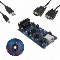
CP2110EK Silicon Laboratories Inc, CP2110EK Datasheet - Page 17

CP2110EK
Manufacturer Part Number
CP2110EK
Description
KIT EVAL FOR CP2110
Manufacturer
Silicon Laboratories Inc
Specifications of CP2110EK
Main Purpose
Interface, USB 2.0 to UART (RS485) Bridge
Embedded
No
Utilized Ic / Part
CP2110
Primary Attributes
Full Speed (12Mbps)
Secondary Attributes
LED Status Indicators
Interface Type
RS-232, USB
Operating Supply Voltage
3.3 V
Product
Interface Development Tools
For Use With/related Products
CP2110
Lead Free Status / RoHS Status
Lead free / RoHS Compliant
Lead Free Status / RoHS Status
Lead free / RoHS Compliant
Other names
336-2003
Available stocks
Company
Part Number
Manufacturer
Quantity
Price
Company:
Part Number:
CP2110EK
Manufacturer:
SiliconL
Quantity:
16
7.3. GPIO.3—RS-485 Transceiver Bus Control
GPIO.3 is configurable as an RS-485 bus transceiver control pin that is connected to the DE and RE inputs of the
transceiver. When configured for RS-485 mode, the pin is asserted during UART data transmission as well as line
break transmission. The RS-485 mode of GPIO.3 is active-high by default, but is also configurable for active-low
mode.
7.4. GPIO.4-5—Transmit and Receive Toggle
GPIO.4 and GPIO.5 are configurable as Transmit Toggle and Receive Toggle pins. These pins are logic high when
a device is not transmitting or receiving data, and they toggle at a fixed rate as specified in Table 6 when data
transfer is in progress. Typically, these pins are connected to two LEDs to indicate data transfer.
More information regarding the configuration and usage of these pins can be found in Section 8 as well as “AN144:
CP21xx Customization Guide” available on the Silicon Labs web site.
Figure 7. Transmit and Receive Toggle Typical Connection Diagram
GPIO.3 – RS485
CP2110
Figure 6. RS-485 Transceiver Typical Connection Diagram
GPIO.5 – RX Toggle
GPIO.4 – TX Toggle
CP2110
RX
TX
Rev. 1.0
R
D
RE
DE
VIO
Transceiver
RS485
CP2110
17


