CP2110EK Silicon Laboratories Inc, CP2110EK Datasheet - Page 8
CP2110EK
Manufacturer Part Number
CP2110EK
Description
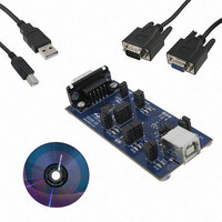
KIT EVAL FOR CP2110
Manufacturer
Silicon Laboratories Inc
Specifications of CP2110EK
Main Purpose
Interface, USB 2.0 to UART (RS485) Bridge
Embedded
No
Utilized Ic / Part
CP2110
Primary Attributes
Full Speed (12Mbps)
Secondary Attributes
LED Status Indicators
Interface Type
RS-232, USB
Operating Supply Voltage
3.3 V
Product
Interface Development Tools
For Use With/related Products
CP2110
Lead Free Status / RoHS Status
Lead free / RoHS Compliant
Lead Free Status / RoHS Status
Lead free / RoHS Compliant
Other names
336-2003
Available stocks
Company
Part Number
Manufacturer
Quantity
Price
Company:

Part Number:
CP2110EK
Manufacturer:
SiliconL
Quantity:
16


CP2110
3. Pinout and Package Definitions
8
*Note: Pins can be left unconnected when not used.
GPIO.0
GPIO.1
GPIO.2
GPIO.3
GPIO.4
REGIN
RS485
Name
VBUS
GND
RST
RTS
CTS
CLK
TXT
V
V
V
RX
D+
D–
TX
DD
PP
IO
Pin #
16*
24*
23*
22*
19*
21
20
1*
6
5
2
9
7
8
3
4
Power Out
Power In
Power In I/O Supply Voltage Input.
Power In 5 V Regulator Input. This pin is the input to the on-chip voltage regulator.
Special
D Out
D Out
D Out
D Out
D Out
Type
D I/O
D I/O
D I/O
D I/O
D I/O
D I/O
D I/O
D I/O
D In
D In
D In
Power Supply Voltage Input.
Voltage Regulator Output. See Section 9.
Ground. Must be tied to ground.
Device Reset. Open-drain output of internal POR or V
source can initiate a system reset by driving this pin low for the time specified
in Table 4.
VBUS Sense Input. This pin should be connected to the VBUS signal of a
USB network.
Connect 4.7 F capacitor between this pin and ground to support ROM
programming via the USB interface.
USB D+
USB D–
Asynchronous data output (UART Transmit) for the UART Interface.
Asynchronous data input (UART Receive) for the UART Interface.
In GPIO mode, this pin is a user-configurable input or output.
In CLK mode, this pin outputs a configurable frequency clock signal.
In GPIO mode, this pin is a user-configurable input or output.
In hardware flow control mode, this pin is the Ready To Send control output
(active low) for the UART interface.
In GPIO mode, this pin is a user-configurable input or output.
In hardware flow control mode, this pin is the Clear To Send control input
(active low) for the UART interface.
In GPIO mode, this pin is a user-configurable input or output.
In RS-485 mode, this pin is the transmit active pin for the RS-485 transceiver.
In GPIO mode, this pin is a user-configurable input or output.
In TXT mode, this pin is the Transmit Toggle pin and toggles to indicate UART
transmission. The pin is logic high when a transmission is not in progress.
Table 7. CP2110 Pin Definitions
Rev. 1.0
Description
DD
monitor. An external
Related parts for CP2110EK
Image
Part Number
Description
Manufacturer
Datasheet
Request
R

Part Number:
Description:
QFN 24/I°/HID USB TO UART BRIDGE
Manufacturer:
Silicon Laboratories Inc

Part Number:
Description:
IC HID USB-TO-UART BRIDGE 24QFN
Manufacturer:
Silicon Laboratories Inc
Datasheet:

Part Number:
Description:
Peripheral Drivers & Components (PCIs) HID USB-UART bridge
Manufacturer:
Silicon Laboratories Inc
Datasheet:
Part Number:
Description:
SMD/C°/SINGLE-ENDED OUTPUT SILICON OSCILLATOR
Manufacturer:
Silicon Laboratories Inc
Part Number:
Description:
Manufacturer:
Silicon Laboratories Inc
Datasheet:
Part Number:
Description:
N/A N/A/SI4010 AES KEYFOB DEMO WITH LCD RX
Manufacturer:
Silicon Laboratories Inc
Datasheet:
Part Number:
Description:
N/A N/A/SI4010 SIMPLIFIED KEY FOB DEMO WITH LED RX
Manufacturer:
Silicon Laboratories Inc
Datasheet:
Part Number:
Description:
N/A/-40 TO 85 OC/EZLINK MODULE; F930/4432 HIGH BAND (REV E/B1)
Manufacturer:
Silicon Laboratories Inc
Part Number:
Description:
EZLink Module; F930/4432 Low Band (rev e/B1)
Manufacturer:
Silicon Laboratories Inc
Part Number:
Description:
I°/4460 10 DBM RADIO TEST CARD 434 MHZ
Manufacturer:
Silicon Laboratories Inc
Part Number:
Description:
I°/4461 14 DBM RADIO TEST CARD 868 MHZ
Manufacturer:
Silicon Laboratories Inc
Part Number:
Description:
I°/4463 20 DBM RFSWITCH RADIO TEST CARD 460 MHZ
Manufacturer:
Silicon Laboratories Inc
Part Number:
Description:
I°/4463 20 DBM RADIO TEST CARD 868 MHZ
Manufacturer:
Silicon Laboratories Inc
Part Number:
Description:
I°/4463 27 DBM RADIO TEST CARD 868 MHZ
Manufacturer:
Silicon Laboratories Inc