LMK04000BEVAL/NOPB National Semiconductor, LMK04000BEVAL/NOPB Datasheet
LMK04000BEVAL/NOPB
Specifications of LMK04000BEVAL/NOPB
LMK04000BEVAL


Related parts for LMK04000BEVAL/NOPB


LMK04000BEVAL/NOPB Summary of contents
Page 1
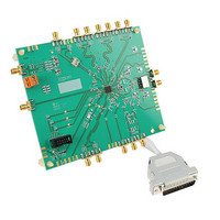
... LMK04000 Family Precision Clock Conditioner with Dual PLLs and Integrated VCO Evaluation Board Operating Instructions for rev3 PCBs National Semiconductor Corporation Precision Timing Devices LMK04000BEVAL LMK04000BEVAL-XO LMK04031BEVAL LMK04031BEVAL-XO LMK04002BEVAL LMK04033BEVAL Interface Division ...
Page 2
Table of Contents T C ....................................................................................................................... 2 ABLE OF ONTENTS G D ................................................................................................................... 4 ENERAL ESCRIPTION Evaluation Board Kit Contents ................................................................................................................................... 4 Available Evaluation Boards ...................................................................................................................................... 4 ...
Page 3
Bill of Material Custom to LMK04000BEVAL ....................................................................................................... 40 Bill of Material Custom to LMK04000BEVAL-XO ................................................................................................ 40 Bill of Material Custom to LMK04031BEVAL ....................................................................................................... 41 Bill of Material ...
Page 4
... National’s website, www.national.com/. • CodeLoader uWire cable (LPT --> uWire). Available Evaluation Boards National Semiconductor has released a series of evaluation boards which allow the customer to evaluate the different output types and VCO frequency ranges made available by the LMK04000 Family. Note possible to mount a VCXO on a –XO board or a Crystal on a non –XO board. See Appendix G: VCXO/Crystal changes for more details ...
Page 5
Available LMK04000 Family NSIDs Please refer to the datasheet for the most up to date list of available devices in the LMK04000 Family. Table 2. LMK040xxB Clock ...
Page 6
... Quick Start Full evaluation board instructions with data are downloadable from the product folder of the device at National Semiconductor’s website, www.national.com/. 1. Connect a voltage of 3.3 volts to either the Vcc SMA connector or the alternate connector. 2. Connect a reference clock from a signal generator or other source. Exact frequency depends on programming ...
Page 7
Default CodeLoader modes for evaluation boards CodeLoader saves the state of the device when exiting the software. To ensure a common starting point, the following modes listed ...
Page 8
Using CodeLoader to Program the LMK040xxB The purpose of this section is to walk the user through using CodeLoader to make some measurements with the LMK040xxB device. ...
Page 9
Program/Load Device Press “Ctrl – L” Assuming the Port Settings are correct now possible to click “Keyboard Controls” “Load Device” from the menu to ...
Page 10
Visual Confirmation of Frequency Lock After a device is selected and a default mode restored and loaded, the visual display on the board should indicate a ...
Page 11
Enable Clock Outputs To measure phase noise at the clock outputs, 1. Click on the “Clock Outputs” tab, 2. Enable an output, 3. Then set the ...
Page 12
PLL Loop Filters and Loop Parameters In jitter cleaning applications that use a cascaded PLL architecture, the first PLL’s purpose is to substitute the phase noise of ...
Page 13
PLL2 Loop Filter 122.88 MHz VCXO (Reference Input) LMK040x0B Charge Pump Current, Kφ Phase Detector Frequency Frequency 1228.8 Kvco 8 ...
Page 14
Evaluation Board Inputs/Outputs The following table contains descriptions of the various inputs and outputs for the evaluation board. Table 5. LMK040xx Evaluation Board I/O Connector Name Input/Output ...
Page 15
Connector Name Input/Output Description CLKin0/CLKin0*, Input CLKin1/CLKin1* LOS0, LOS1 Output OSCin/OSCin* Input ...
Page 16
Connector Name Input/Output Description Vtune1 Output uWire Input/Output LD Output LD_TP Output GOE Input SYNC* Input PTO Output ...
Page 17
Recommended Test Equipment Power Supply The Power Supply should be a low noise power supply. Phase Noise / Spectrum Analyzer For measuring phase noise an Agilent E5052A ...
Page 18
Appendix A: CodeLoader Usage Code Loader is used to program the evaluation board with either an LPT port using the included CodeLoader cable or with a USB ...
Page 19
Clock Outputs Tab The clock outputs tab allows the user to Enable/Disable individual clock outputs, select the clock mode (Bypass/Divided/Delayed/Divided & Delayed), set the clock output delay ...
Page 20
PLL1 Tab The PLL1 tab allows the user to change: • External VCXO (or Crystal oscillator) frequency. Note: This value must be entered in both the PLL1 ...
Page 21
PLL2 Tab The PLL2 tab allows the user to change: • VCO frequency • PLL2 Phase detector frequency • PLL2 R-counter value • PLL2 N-counter value • ...
Page 22
Bits/Pins Tab The Bits/Pins tab allows the user to program bits directly. Many of which are not available on other tabs. Refer to the datasheet for more ...
Page 23
• CLKin Options Box o CLKin_SEL – Sets manual or automatic switching modes for selecting a reference oscillator for PLL1. o LOS_TIMEOUT – The timeout value before ...
Page 24
Registers Tab The registers tab shows the value of each register. This is convenient for programming the device to the desired settings, then recording the hex values ...
Page 25
Appendix B: Typical Phase Noise Performance Plots PLL1 The LMK040xxB’s two stage jitter cleaning process involves masking the reference noise with a VCXO or Crystal. Therefore the ...
Page 26
Vectron 12.288 MHz Crystal The phase noise of the reference is masked by the phase noise of the crystal by using a narrow loop bandwidth. The crystal ...
Page 27
PLL2 The closed loop performance of the system as measured at the VCO output Fout. Fout phase noise performance of the various LMK options is plotted in ...
Page 28
Clock Outputs The LMK04000 Family features LVDS, LVPECL, 2VPECL, and LVCMOS types of outputs. Included below are various phase noise measurements for each output. Device LVDS LMK040x0B ...
Page 29
LMK040x0B Phase Noise -50 -60 -70 -80 -90 -100 -110 -120 -130 -140 -150 -160 -170 10 100 Figure 16 - LMK040x0B Phase Noise The Fout frequency ...
Page 30
LMK040x1B Phase Noise LMK040x1B Phase Noise -50 -60 -70 -80 -90 -100 -110 -120 -130 -140 -150 -160 -170 10 100 Figure 17 - LMK040x1B Phase Noise ...
Page 31
LMK040x2B Phase Noise -50 -60 -70 -80 -90 -100 -110 -120 -130 -140 -150 -160 -170 10 100 The Fout frequency is 1720.32 MHz. The clock out ...
Page 32
LMK040x3B Phase Noise LMK040x3B Phase Noise -50 -60 -70 -80 -90 -100 -110 -120 -130 -140 -150 -160 -170 10 100 The Fout frequency is 1966.08 MHz. ...
Page 33
Appendix C: Schematics Power Direct Power Vcc VccPLLPlane R1 Vcc SMA 0 ohm VccCLKoutPlane R2 0 ohm ...
Page 34
Main Fout Balun and Impedance Matching CLKout4_P CLKout4_N Fout SMA C24 R5 18 ohm 100 pF R6 ...
Page 35
Clock Outputs CLKout0 Output option 0 - LVPECL/2VPECL Output option 1 - LVPECL/2VPECL VccCLKoutPlane Output option 3 ...
Page 36
Appendix D: Board Layers Stackup Layers of the 6 layer evaluation board include: Blue is dielectrics • ...
Page 37
Appendix E: Bill of Materials Common Bill of Materials for Evaluation Boards Part Manufacturer Capacitors 33 pF ...
Page 38
Common Bill of Materials for Evaluation Boards (continued, 2/3) Resistors 0 ohm Vishay/Dale 18 ohm Vishay/Dale 51 ...
Page 39
Common Bill of Materials for Evaluation Boards (continued, 3/3) Open Open Open Open Open Open Open Open ...
Page 40
... National Semiconductor CVHD-950-122.88 Crystek Open Open Open Bill of Material Custom to LMK04000BEVAL-XO Part Manufacturer Capacitors Resistors 0 ohm Vishay/Dale 120 ohm Vishay/Dale Other LMK04000B National Semiconductor 12.288 MHz XTAL Vectron Open Open Open Open Part Number C0603C104J3RAC CRCW06030000Z0EA CRCW0603120RJNEA LMK04000B CVHD-950-122.88 Part Number ...
Page 41
... National Semiconductor CVHD-950-122.88 Crystek Open Open Open Bill of Material Custom to LMK04031BEVAL-XO Part Manufacturer Capacitors Resistors 0 ohm Vishay/Dale 120 ohm Vishay/Dale Other LMK04031B National Semiconductor 12.288 MHz XTAL Vectron Open Open Open Open Part Number C0603C104J3RAC CRCW06030000Z0EA CRCW0603120RJNEA LMK04031B CVHD-950-122.88 Part Number ...
Page 42
... CVHD-950-122.88 Crystek Open Open Open Bill of Material Custom to LMK04033BEVAL Part Manufacturer Capacitors 0.1 uF Kemet Resistors 0 ohm Vishay/Dale 120 ohm Vishay/Dale Other LMK04033B National Semiconductor CVHD-950-122.88 Crystek Open Open Open Part Number C0603C104J3RAC CRCW06030000Z0EA CRCW0603120RJNEA LMK04002B CVHD-950-122.88 Part Number C0603C104J3RAC CRCW06030000Z0EA CRCW0603120RJNEA LMK04033B CVHD-950-122 ...
Page 43
Appendix F: Balun Information Typical Balun Frequency Response The following figure illustrates the typical frequency response of the Mini-circuit’s ADT2-1T balun. Figure 18 - Typical Balun Frequency ...
Page 44
Appendix G: VCXO/Crystal changes This appendix contains instructions for changing the active on-board oscillator for PLL1. Changing from Crystal Resonator to VCXO If the board has been ...
Page 45
Disconnect Crystal RF path and connect VCXO RF path a. Remove resistors R15 and R31. b. Install 0.1 uF capacitors in C31 and C43. Figure 20 ...
Page 46
Connect charge pump output from PLL2 to VCXO Loop filter (A2). a. Remove R10 and install a 0 ohm resistor in R9. This resistor can be ...
Page 47
Changing from VCXO to Crystal Resonator If the board has been setup to use the VCXO for PLL1, the VCXO may be disabled and the crystal enabled ...
Page 48
Disconnect VCXO RF path and connect Crystal RF path a. Install 0 ohm resistors R15 and R31. b. Remove 0.1 uF capacitors in C31 and C43. ...
Page 49
Connect charge pump output from PLL2 to Crystal Loop filter (B2) a. Remove R9 and install a 0 ohm resistor in R10. This resistor can be ...
Page 50
Appendix H: LMK04000 The block diagram in Figure 27 illustrates the functional architecture of the LMK040xxB clock conditioner. It features a cascaded, dual PLL arrangement, available internal ...
Page 51
PLL1 has been designed to work with either an off-the-shelf VCXO package or with a user- designed discrete implementation that employs a crystal resonator and associated tuning ...
Page 52
Figure 29 - Crystal Oscillator Circuit diagram ...
Page 53
Appendix I: Properly Configuring LPT Port When trying to solve any communications issue convenient to program the POWERDOWN bit to confirm high/low current draw of ...
Page 54
Figure 31 - Selecting the LPT Port Correct LPT Mode If communications are not working, then it is possible the LPT port mode is set improperly. It ...
Page 55
Appendix J: Troubleshooting Information If the evaluation board is not behaving as expected, the most likely issues are… 1) Board communication issue 2) Incorrect Programming of the ...
Page 56
pin output is low, but the frequencies are the same possible that excessive leakage on Vtune pin is causing the digital lock ...